Quick Answer
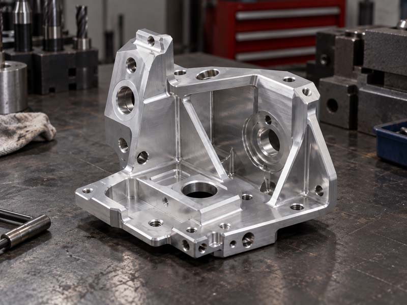
Deep pockets are features with a depth significantly greater than their width or opening, typically where the depth-to-diameter or depth-to-width ratio exceeds 3:1. In CNC milling, deep pockets increase tool stick-out, reduce rigidity, and raise the risk of deflection, chatter, and poor surface finish. To improve machinability, designers should increase internal corner radii where functionally possible, limit pocket depth relative to tool reach, specify wider tolerances on non-critical walls, and consider splitting deep pockets into shallower segments or using 5-axis machining to reduce tool extension. Providing a detailed 2D drawing with critical tolerances, datum references, and surface finish callouts helps the supplier select the correct strategy and avoid unexpected costs.
Key Takeaways
- Avoid depth-to-width ratios above 4:1 for standard tooling; deeper pockets require special long-reach cutters or alternative processes like EDM or 5-axis milling.
- Increase internal corner radii to at least 2x the pocket depth, or as large as function allows, so that a larger-diameter, more rigid cutter can be used.
- Thin walls around deep pockets are prone to vibration and deformation; maintain a minimum wall thickness of at least 1.5 mm for aluminum and more for harder materials.
- Specify as-machined surface finish parameters (Ra 1.6–3.2 μm) on side walls of deep pockets; tighter finishes may require secondary operations that increase cycle time.
- Communicate the pocket depth, minimum internal radius, and any critical tolerances in your 2D drawing to allow the CNC machining supplier to plan tool paths, estimate cycle time, and avoid rework.
Why Deep Pockets Are Challenging in CNC Milling
In CNC milling, a pocket is considered deep when the ratio of its depth (D) to its smallest opening width (W) exceeds a certain threshold. Common industry experience suggests that any pocket with D/W > 3:1 requires careful consideration. The fundamental problem is that deeper pockets force the cutting tool to extend further from the spindle (increased stick-out), which reduces the tool's rigidity. A less rigid cutter is more susceptible to deflection under cutting forces, leading to geometric inaccuracies on the side walls and a rougher surface finish. Additionally, chip evacuation becomes more difficult in deep cavities, increasing the risk of chip re-cutting, heat buildup, and tool wear.
Beyond tooling concerns, deep pockets often involve thin side walls. Thin walls can deflect elastically or plastically during machining, making it hard to hold tight tolerances. The combination of long tool reach, thin wall sections, and high material removal rates can also cause chatter, a self-excited vibration that degrades surface quality and may lead to tool breakage.
Depth-to-Width Ratio and Tool Selection
The depth-to-width (or depth-to-diameter) ratio is the primary factor that determines whether a pocket can be machined with standard end mills or requires specialty tooling. For example, a 20 mm wide pocket that is 80 mm deep has a ratio of 4:1. Most standard end mills have a maximum usable length equal to about 3–4 times their diameter. To reach 80 mm depth in a 20 mm pocket, the tool diameter cannot exceed 20 mm, so a 20 mm end mill with 80 mm reach has a stick-out ratio of 4:1, which is already near the practical limit for many materials. If the corner radius is very small, the tool diameter must be even smaller, worsening the ratio.
Below is a general reference table that relates depth-to-width ratio to machining difficulty and tooling considerations. This is not a fixed guarantee but a typical engineering guideline.
| D/W Ratio | Machining Difficulty | Typical Tooling | Considerations |
|---|---|---|---|
| ≤ 2:1 | Low | Standard end mill | Good rigidity; standard feeds and speeds; minimal issues. |
| 2:1 to 3:1 | Moderate | Standard or slightly extended | Reduce feed rate; use roughing and finishing passes; monitor surface finish. |
| 3:1 to 5:1 | High | Long-reach end mill or necked tool | Significantly reduce depth of cut; use smaller stepovers; consider 5-axis to tilt tool. |
| 5:1 to 8:1 | Very High | Precision extended reach; possible custom tool | Must use progressive roughing; likely need multiple setups; consider wire EDM for tight corners. |
| > 8:1 | Extreme | Specialized tooling or alternative process | May require 5-axis posture milling, or break the pocket into segments; high cost and lead time. |
Internal Corner Radius and Cutter Diameter
The internal corner radius of a pocket directly determines the maximum diameter of the end mill that can clean the corner without leaving material. If your design specifies a sharp internal corner (e.g., R0.5 mm), the cutter diameter must be ≤ 1 mm (or use a small corner radius end mill). Such a small tool is very fragile and must run at high speed with very low material removal rates, dramatically increasing cycle time and cost. Conversely, specifying a larger internal radius, such as R5 mm, allows the use of a 10 mm end mill (or larger) that is much more rigid and efficient.
Design recommendation: Where function permits, specify internal corner radii equal to at least 0.05 × pocket depth, or a minimum of 3 mm for depths up to 60 mm. For deeper pockets, increase the radius proportionally. This single change can cut machining time by 30–50%.
Wall Thickness and Part Rigidity
Thin walls surrounding deep pockets are prone to deflection and vibration during milling. The wall thickness should be sufficient to resist cutting forces without significant elastic deformation. As a general engineering guideline, for aluminum parts, maintain a minimum wall thickness of 1.5 to 2.0 mm for depths up to 100 mm. For stainless steel or titanium, increase to at least 2.5–3.0 mm. If the pocket is very deep (over 100 mm) or the walls are tall, consider thickening the walls or adding ribs to increase stiffness.
When thin walls are unavoidable, discuss with your CNC machining provider whether using a specialized workholding strategy (e.g., filling the pocket with low-melt alloy or using vibration-damping fixturing) can help maintain tolerances.
Chip Evacuation and Coolant Access
In deep pockets, chips cannot easily escape the cutting zone. Poor chip evacuation leads to re-cutting of chips, increased tool wear, and heat buildup. Designers can help by incorporating features that allow coolant or air blast to reach the cutting zone. For example, avoid sharp corners at the bottom of the pocket that can trap chips; use a slightly radiused floor-wall intersection. If the part design allows, adding a small through-hole at the bottom of the pocket can provide an escape path for coolant and chips, though this must be functionally acceptable.
The machining team may use through-spindle coolant, high-pressure coolant, or air blast to assist evacuation. In very deep pockets, they may need to employ peck milling cycles to clear chips periodically, which increases cycle time.
Impact on Cost and Lead Time
Deep pockets significantly increase machining cost due to longer cycle times, special tooling, and multiple passes. The following factors contribute to cost escalation:
- Longer cutting time: Low material removal rates and multiple finishing passes add time.
- Special tools: Extended-reach end mills cost more and may need coatings.
- Increased setups: Sometimes the pocket must be machined from both sides to achieve the final depth.
- Higher scrap risk: If tool deflection exceeds tolerances, parts may be scrapped.
- Secondary operations: Tight surface finish requirements may demand polishing or EDM.
To estimate cost, provide your precision machining partner with the critical dimensions: depth, width, corner radius, wall thickness, and material. They will calculate the expected cycle time and tool cost.
Design Strategies for Better Deep Pocket Machinability
1. Split Deep Pockets into Shallower Segments
If your design allows, divide a single deep pocket into multiple shallower pockets separated by ribs or pads. This reduces the tool reach requirement per pocket and allows using larger, more rigid cutters. For example, a 120 mm deep pocket could be designed as two 60 mm deep pockets with a 5 mm thick web between them (if structural). This can reduce machining time by up to 40%.
2. Use Tapered Side Walls
Draft angles or tapered walls (e.g., 1–2 degrees) can improve tool access and reduce the effective depth from the perspective of the cutting edges. Tapered walls also help in ejection from molds, but for machined pockets, they provide clearance for the tool body.
3. Reduce Tolerances on Non-Critical Walls
Only specify tight tolerances on features that mate with other parts. For deep pocket side walls that are not functional surfaces, relax the tolerance to ±0.2 mm or more. This allows the supplier to use a more aggressive tool path without secondary finishing passes.
4. Avoid Deep Bottoms with Flat Corners
Flat-bottom corners at the pocket floor require a tool with a flat cutting edge or a corner radius end mill. If the floor must be flat, allow a small radius (0.1–0.5 mm) or specify that the corner may have a small radius (typically acceptable as long as it's defined on the drawing).
5. Consider 5-Axis Machining
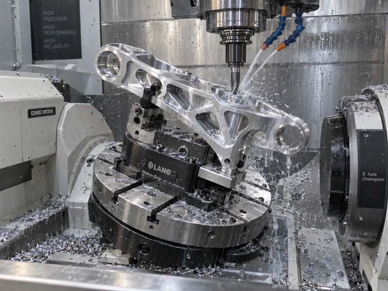
For very deep pockets, 5-axis CNC machining allows tilting the tool so that effective stick-out is reduced, and more of the flank of the cutter engages the material. 5-axis machining can also accomplish deeper pockets with fewer setups and better surface finish, though the hourly rate may be higher.
What This Means for Your Part
If your design involves deep pockets, start by reviewing the depth-to-width ratio and internal corner radius. Ask yourself: are these dimensions functionally necessary? Can any radius be increased? Are the wall thicknesses sufficient to avoid vibration? Then, before sending the RFQ, prepare a clear 2D drawing that highlights the pocket depth, minimum corner radii, critical tolerances, and surface finish requirements. Provide a 3D model in STEP format, but do not assume the supplier can interpret all requirements from the model alone.
Communicating these details upfront allows the CNC machining shop to choose the best tool path strategy, estimate a realistic lead time, and give you a competitive quote. For assistance with DFM review, submit your design for a machining feasibility assessment.