Introduction: Why Aluminum Dominates CNC Machining
Aluminum is one of the most widely used materials in CNC machining due to its excellent strength-to-weight ratio, corrosion resistance, thermal conductivity, and machinability. From aerospace brackets to electronic enclosures, CNC-machined aluminum parts are found across countless industries. However, achieving high-quality, cost-effective results requires a solid understanding of material behavior, design rules, tolerance capabilities, and finishing options. This guide provides a comprehensive overview for engineers, designers, and procurement professionals looking to optimize their aluminum CNC projects.
Material Selection: Choosing the Right Aluminum Alloy
The most common aluminum alloys for CNC machining are 6061, 7075, 2024, and 5083. Each offers distinct properties:
6061 Aluminum
6061 is the workhorse alloy for general-purpose machining. It offers good strength, excellent corrosion resistance, and easy machinability. It welds well and is available in various tempers (e.g., T6). Ideal for structural components, enclosures, and automotive parts.
7075 Aluminum
With strength comparable to many steels, 7075 is used in high-stress applications like aerospace frames and racing components. It is more difficult to machine than 6061 and requires sharper tools and lower speeds. It has lower corrosion resistance and is often anodized or coated.
2024 & 5083
2024 offers high fatigue strength but poor corrosion resistance; 5083 is excellent for marine environments. Both are machinable but require appropriate tooling and coolant strategies.
When selecting an alloy, consider mechanical requirements, environmental exposure, cost, and machinability. For most projects, 6061–T6 offers the best balance.
Design for Machining (DFM) Principles for Aluminum Parts
Designing parts that are easy to machine reduces cycle time, tool wear, and cost. Key DFM guidelines for aluminum:
Wall Thickness & Ribs
Thin walls (below 0.5 mm) can vibrate during milling, leading to poor surface finish and dimensional errors. A minimum wall thickness of 1.5 mm is recommended for structural rigidity. Ribs should have adequate draft angles if die-cast, but for machined parts, straight walls with fillets are best.
Internal Corners & Fillets
Sharp internal corners cannot be cut with a rotating tool; the tool radius leaves a fillet. Design internal radii at least 0.5–1.5 mm, preferably 3 mm or more to allow larger tools and faster material removal. Avoid right-angle pockets.
Undercuts & Features
Undercuts require special tools (lollipop cutters) or EDM, increasing cost. Where possible, orient undercuts in a single direction or eliminate them. Deep narrow slots (depth > 4× width) are difficult to machine; use open designs or reduce depth.
Threaded Holes
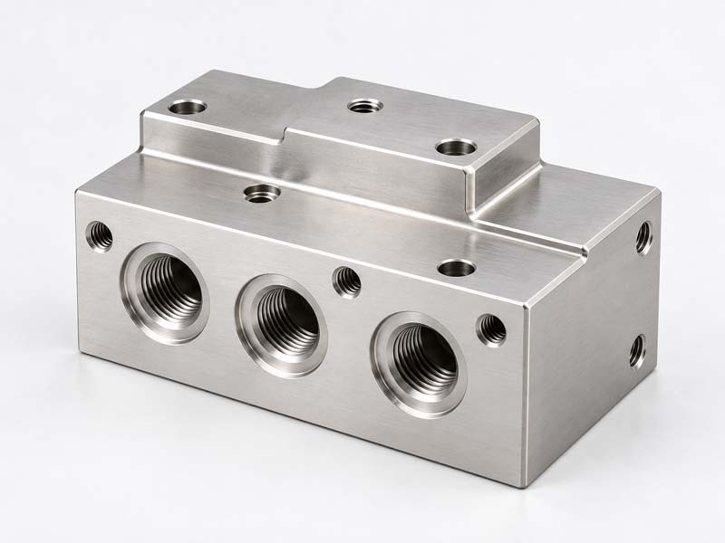
For threads in aluminum, use thread inserts (Heli-Coil) for high strength, or tap directly for low-load applications. Avoid blind holes with small tap diameters (below M2) as taps break easily. Specify thread depth relative to nominal diameter.
Tolerances & Fits in Aluminum Machining
Aluminum’s high thermal expansion coefficient (23 μm/m·°C) affects tolerances during machining and in service. Standard CNC machining can hold ±0.1 mm (general) to ±0.025 mm (precision). For tighter fits, consider temperature control in the shop and design for operating conditions.
Common Tolerance Grades
Machining tolerances are often specified using ISO 2768 (general tolerances) or custom GD&T. For aluminum, typical achievable tolerances:
- Linear dimensions: ±0.1 mm (standard), ±0.02 mm (precision)
- Hole diameters: ±0.02 mm (drilled), ±0.01 mm (reamed)
- Flatness: 0.05 mm per 100 mm
- Concentricity: 0.03 mm (on turned parts)
For press-fits or sliding fits (e.g., bearings in housings), use interference or clearance classes based on ISO 286. Note that aluminum can gall under high-pressure contacts; consider anodizing or steel bushings.
Surface Finishes for CNC Aluminum Parts
As-machined aluminum has visible tool marks and a matte appearance. Common post-machining finishes include:
As-Machined
Suitable for internal components where aesthetics don’t matter. Surface roughness typically Ra 0.8–3.2 μm depending on toolpath and stepover.
Anodizing (Type II & III)
Anodizing creates a hard, corrosion-resistant oxide layer. Type II (decorative) offers colors; Type III (hardcoat) is thicker (25–75 μm) and improves wear resistance. Tolerances can shift up to half the coating thickness, so allow for growth.
Bead Blasting
Creates a uniform matte finish and hides minor imperfections. Typically followed by anodizing for protection. Bead blasting can alter dimensions slightly, so avoid on tight tolerance faces.
Other Options
Polishing (high luster), powder coating (thicker, for heavy-duty environments), and chemical conversion coating (chromate or trivalent) for electrical conductivity and paint adhesion.
Inspection & Quality Control
Reliable inspection ensures parts meet specifications. Common methods for aluminum parts:
- CMM (Coordinate Measuring Machine): Accurate to microns, suitable for complex geometries and GD&T.
- Height gauges & micrometers: For quick verification of critical dimensions.
- Thread gauges: GO/NO-GO for threaded features.
- Surface roughness testers: To verify Ra/Rz values.
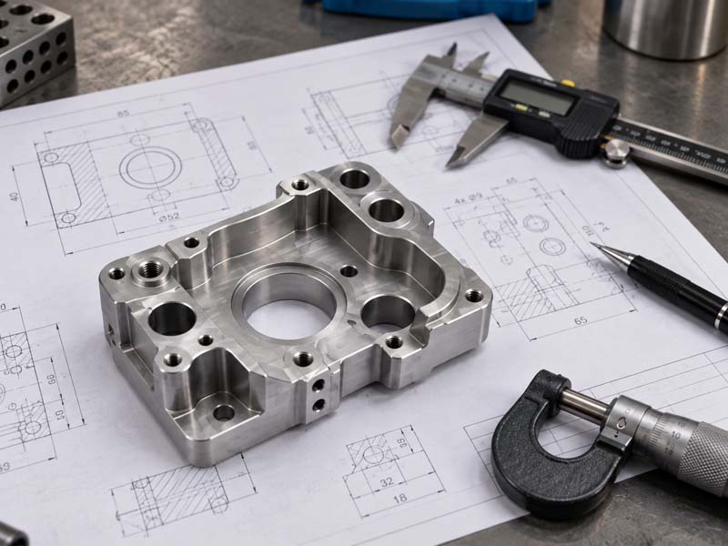
When working with a CNC shop like Hongke CNC, always request a dimensional inspection report (FAI) for first articles. This verifies that the machining process produces parts within tolerance before full production.
Practical Case Study: Machining a Complex Bracket
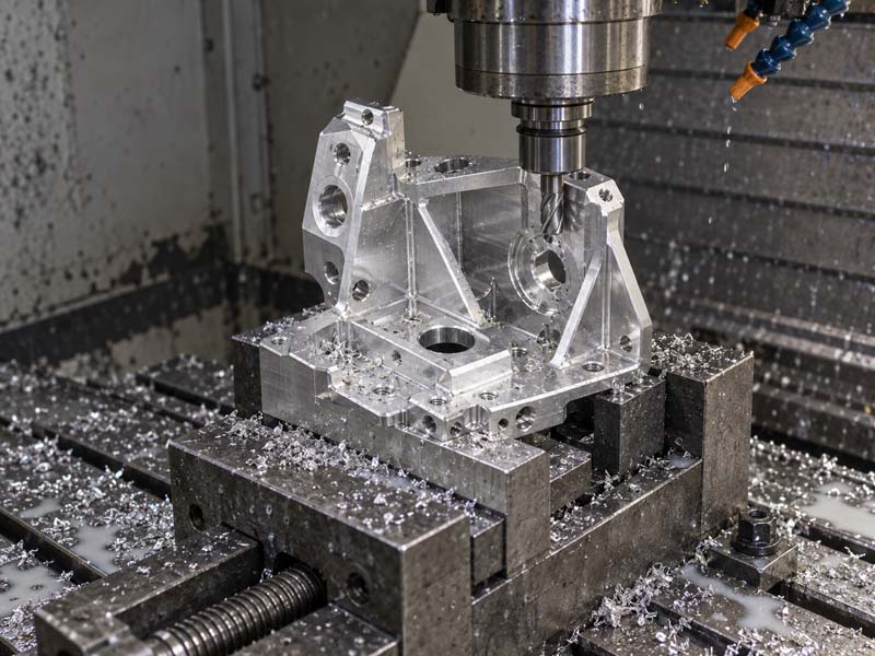
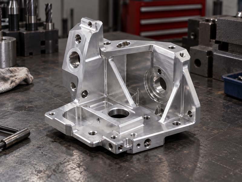
Consider an aluminum bracket with multiple mounting holes, internal cavities, and a thin wall section. Applying DFM principles: the design incorporates 3 mm internal fillets, uniform wall thickness of 2 mm, and threaded inserts for M4 screws. The alloy chosen is 6061–T6. Tolerances are ±0.05 mm on hole centers and ±0.1 mm on overall dimensions. After machining, the bracket is bead blasted and Type II anodized in black. CMM inspection confirms all features are within spec. This approach minimizes material waste, speeds up machining (single setup on a 5-axis CNC), and ensures long-term corrosion resistance.
Conclusion & Partnering with a Reliable CNC Shop
Successful aluminum CNC machining requires a holistic understanding of materials, design constraints, tolerance capabilities, and finishing choices. By working closely with an experienced manufacturer that can provide DFM feedback, you can avoid costly revisions and achieve superior part quality.
Hongke CNC specializes in precision machining of aluminum components, offering advanced 3-axis, 4-axis, and 5-axis CNC mills, CMM inspection, and a range of surface finishes. Our engineering team collaborates from prototype to production to ensure your designs are optimized for manufacturability and performance.
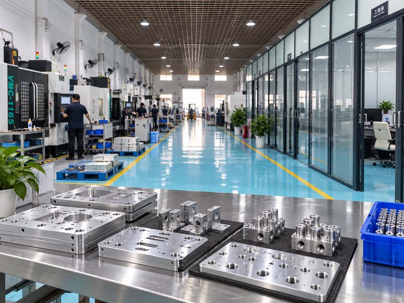
Whether you need a single prototype or high-volume production, applying the guidelines in this article will help you achieve consistent, high-quality aluminum parts. Contact us to discuss your next project.