Introduction: Why Design for Machinability Matters
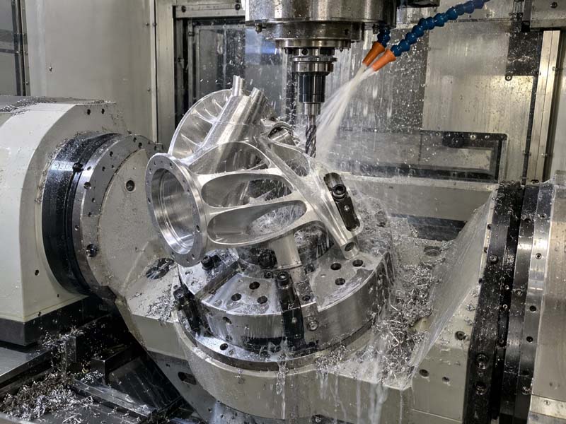
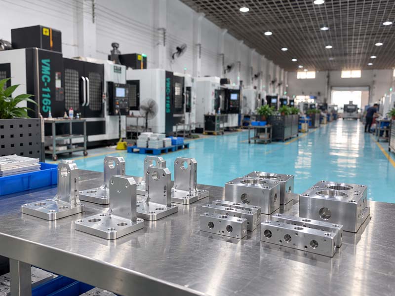
In CNC machining, the design of a part directly determines its cost, lead time, and quality. Design for Manufacturability (DFM) is a set of principles that help engineers create parts that are easy and cost-effective to machine while maintaining functionality. By following these guidelines, you can avoid common pitfalls such as excessive material removal, complex setups, and tight tolerances that drive up expenses. This guide covers essential DFM rules for CNC machining, including feature design, material selection, and tolerance strategies.
1. Corner Radii and Internal Geometry
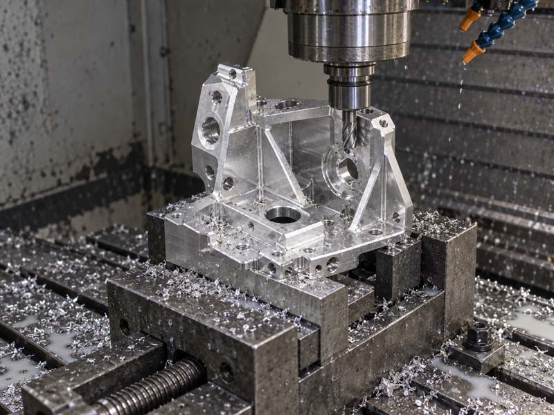
Sharp internal corners are a major challenge in CNC milling. Cutting tools are cylindrical, so they cannot cut a perfect 90-degree internal corner without leaving a radius. The rule of thumb is to design internal corners with a radius of at least 1/3 of the cavity depth or larger. For example, a 10 mm deep pocket should have a corner radius of at least 3 mm. This allows using a larger diameter tool, which is more rigid and can achieve higher material removal rates.
If sharp corners are absolutely necessary, consider adding relief cuts or using wire EDM for those features. Always consult with your machining partner like Hongke CNC to understand tooling limitations early in the design phase.
Key Guidelines for Internal Corners:
- Minimum corner radius: 0.5 mm for shallow pockets, but larger is better.
- For deep pockets, use radii > 6 mm to avoid long tool overhangs.
- Avoid completely sharp internal corners; use fillets or chamfers.
2. Wall Thickness and Feature Size
Thin walls can vibrate during machining, leading to poor surface finish and dimensional inaccuracies. A general rule is to maintain a minimum wall thickness of 0.5 mm for metals like aluminum and 1 mm for harder materials like steel. For plastics, thickness should be at least 1.5 mm to prevent melting or chattering.
Features like ribs and bosses should be proportioned correctly. Deep, narrow slots are difficult to machine because of tool deflection. The depth-to-width ratio for slots should not exceed 5:1. For example, a 2 mm wide slot should not be deeper than 10 mm.
3. Hole Design and Threads
Holes are common features, but their design affects machining cost. Standard drill sizes reduce the need for special tooling. Use metric or imperial standard diameters. For threaded holes, specify thread depth correctly: for blind holes, provide extra depth for the tap (typically 3-5 threads beyond the required engagement). Avoid threading to the bottom of a blind hole unless necessary, as tap breakage risk increases.
Through holes are easier to machine than blind holes because chips can exit freely. If a blind hole is required, ensure the bottom has a conical shape from the drill point (118° or 135° angle).
Best Practices for Holes:
- Use standard drill sizes (e.g., 3, 4, 5, 6, 8, 10 mm).
- Specify thread depth with a min. 2-3 extra threads in blind holes.
- Avoid very small holes (< 1 mm) in hard materials; they break easily.
4. Tolerance Sensitivity
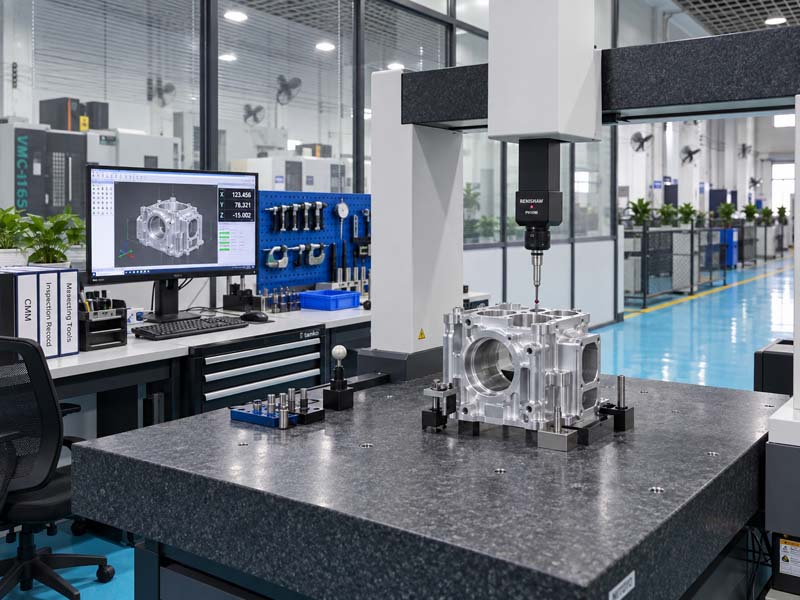
Specifying unnecessarily tight tolerances is one of the biggest cost drivers in CNC machining. Tight tolerances require slower speeds, multiple passes, and inspection time. A typical CNC machining tolerance for general applications is ±0.1 mm, while precision work can achieve ±0.025 mm. Only use tight tolerances where functional fit or assembly requires it.
It's also important to understand geometric dimensioning and tolerancing (GD&T). Features like flatness, parallelism, and concentricity should be specified only when critical. Avoid applying tight tolerances to non-critical surfaces or large areas.
5. Material Selection and Machinability
Different materials machine differently. Aluminum alloys like 6061 and 7075 are excellent for machining due to their low hardness and good chip formation. Brass and free-machining steels (like 12L14) are also easy to machine. Stainless steels (e.g., 304, 316) are tougher and require slower speeds, increasing cost. Engineering plastics like Delrin and Nylon are easy to machine but may require sharp tools.
If your design can accommodate alternative material, consult your CNC machining service provider to choose the most cost-effective option. For prototype runs, aluminum is often the best balance of strength, weight, and machinability.
6. Surface Finish Considerations
Surface finish (Ra value) impacts cost. A standard machined finish (Ra 3.2 µm or 125 µin) is suitable for most parts. If you need a smoother finish (Ra 0.8 µm), additional polishing or finer tool passes are required. Avoid specifying very fine finishes on complex internal surfaces unless necessary.
For cosmetic appearance, post-processing like bead blasting or anodizing can be applied. Anodizing also adds wear resistance. Remember that the surface finish requirement should be matched with the material; for example, aluminum can achieve better finishes than cast iron.
7. Design Checklist for DFM
Before finalizing your CAD model, run through this checklist:
- Avoid sharp internal corners; use appropriate radii.
- Maintain consistent wall thickness (avoid thick-to-thin transitions).
- Use standard sizes for holes, threads, and tool diameters.
- Specify tolerances only where necessary.
- Design features that can be machined from one setup if possible.
- Avoid deep cavities and narrow slots.
- Consider adding chamfers or countersinks to ease assembly.
- Provide enough material for fixturing (clamping areas).
Conclusion
Applying DFM principles early in the design phase can significantly reduce CNC machining costs, improve part quality, and shorten lead times. By cooperating with an experienced machining partner like Hongke CNC, you can get valuable feedback on your design and ensure a smooth transition from prototype to production. Remember that every design decision has machining implications — use this guide to make informed choices.