
Multi-Side Machining
Reduce repeated setups while keeping related features connected to one datum plan.
Drawing-led process planning for multi-side geometry, compound angles, complex contours and difficult tool access, supported by datum, fixture, collision and inspection review.
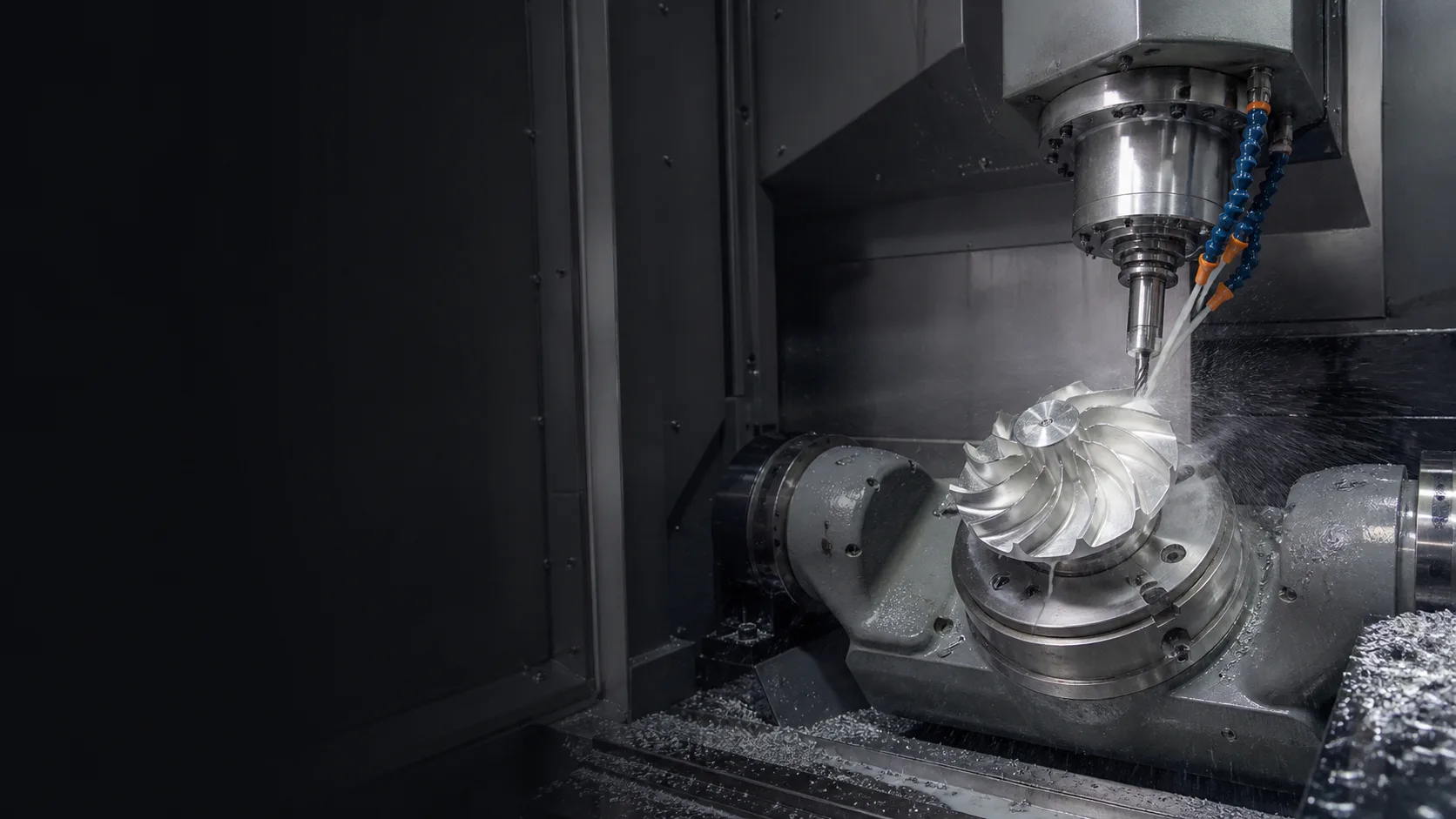
5-Axis Strategy ReviewMachining route selected from the drawing
Complex Multi-Side GeometryRelated features across faces
DFM & Tool Access ReviewClearance checked before setup
Inspection & ReportsDocumentation confirmed by project
Use five-axis planning where orientation, access and feature relationships create more risk than the part's overall complexity alone.
Reduce repeated setups while keeping related features connected to one datum plan.
Reach angled holes, faces and interfaces without building a separate fixture for every orientation.
Approach restricted features with shorter, more stable tooling where geometry permits.
Plan changing tool orientation for contours and freeform surfaces that require controlled contact.
Limit datum transfer and accumulated setup error across connected critical features.
Not every complex part requires simultaneous 5-axis machining. The machining strategy should be selected according to geometry, datum relationships, tool access, tolerances and surface requirements. A conventional CNC milling route may be the better choice.
The review separates positioning needs from continuous tool motion, then checks access, fixture and inspection consequences.
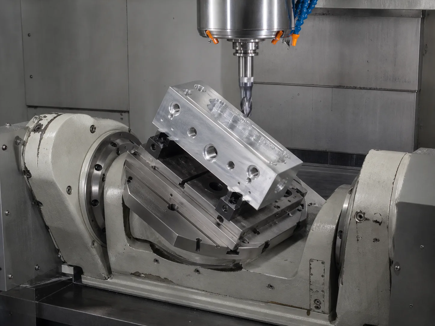
Position the rotary axes between cuts when several angled faces need access without continuous rotary interpolation.
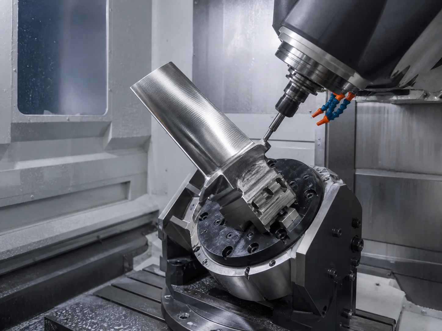
Evaluate continuously changing tool orientation for freeform surfaces, complex contours and controlled contact paths.
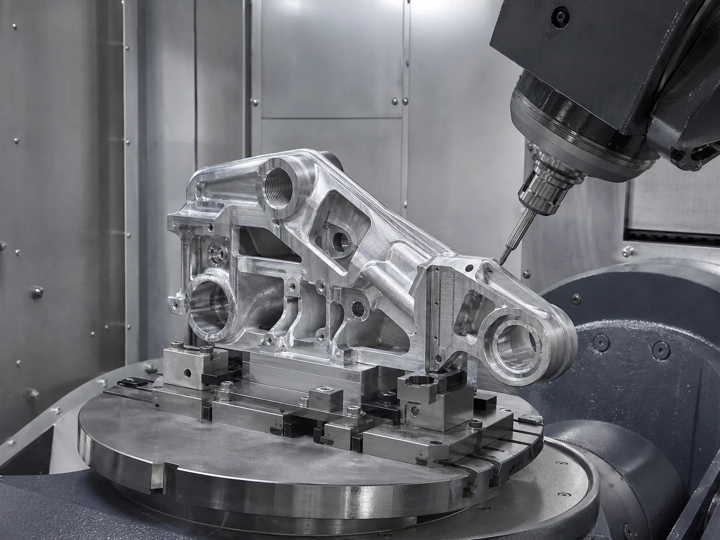
Protect position and orientation relationships between bores, pockets, mating faces and side features.
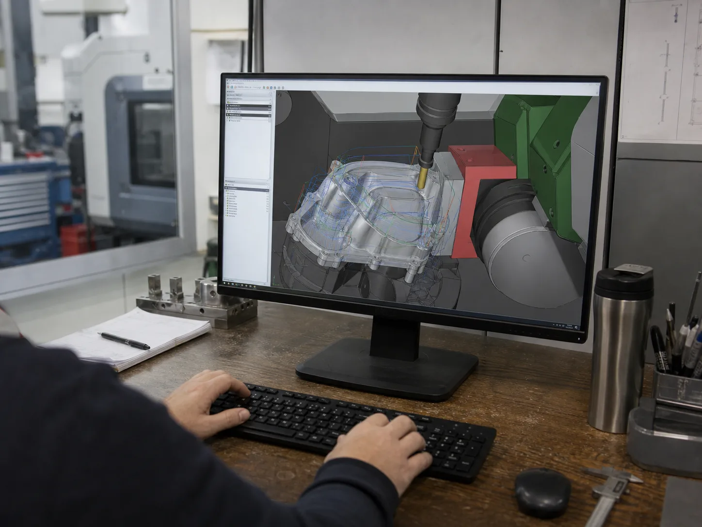
Review tool reach, holder clearance, fixture interference, rotary travel and collision risk before release.
These examples explain geometry that may benefit from multi-axis review. They are not customer project records or order-specific capability evidence.
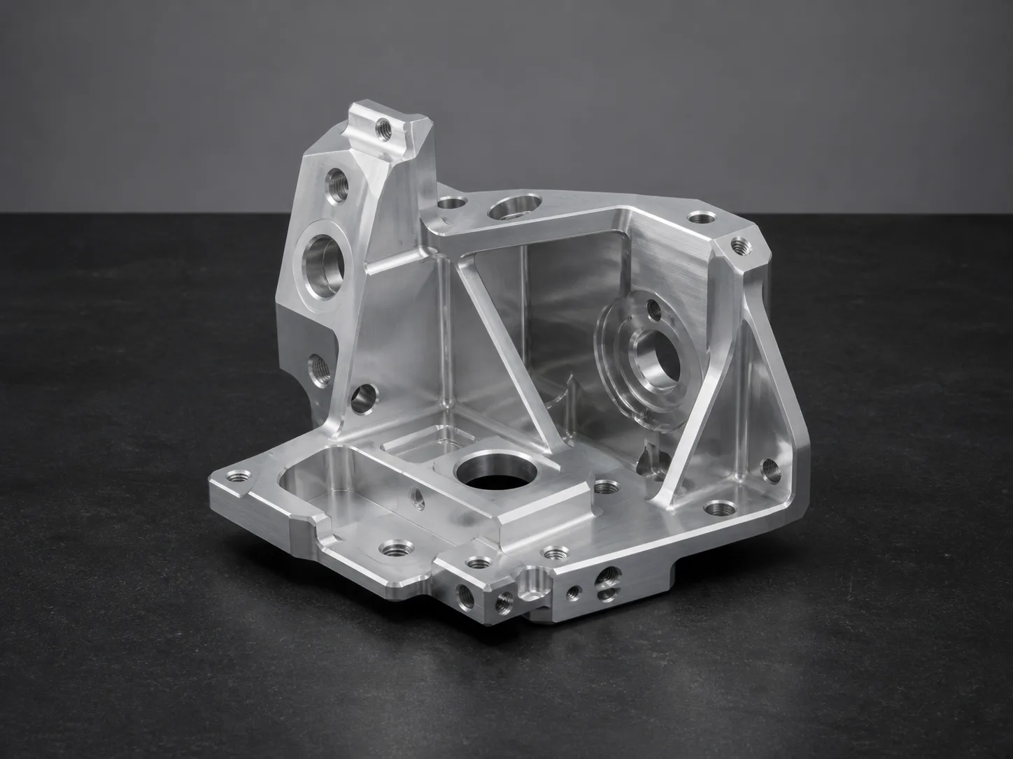
Review focus: datum continuity across faces, angled holes, restricted pockets, thin ribs and fixture access.
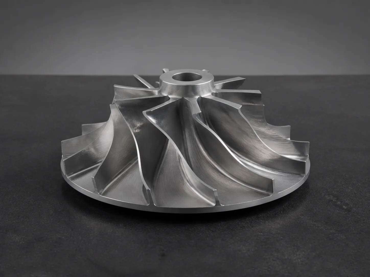
Review focus: changing surface normals, blade-to-hub transitions, tool contact, reach and profile inspection.
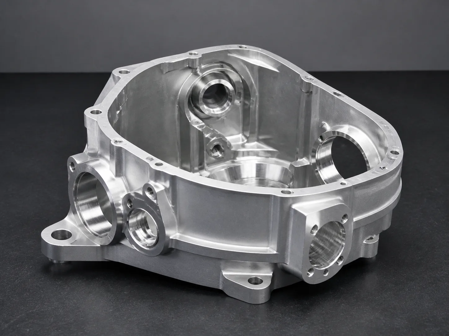
Review focus: deep-cavity access, intersecting angled ports, mating faces and measurable feature relationships.
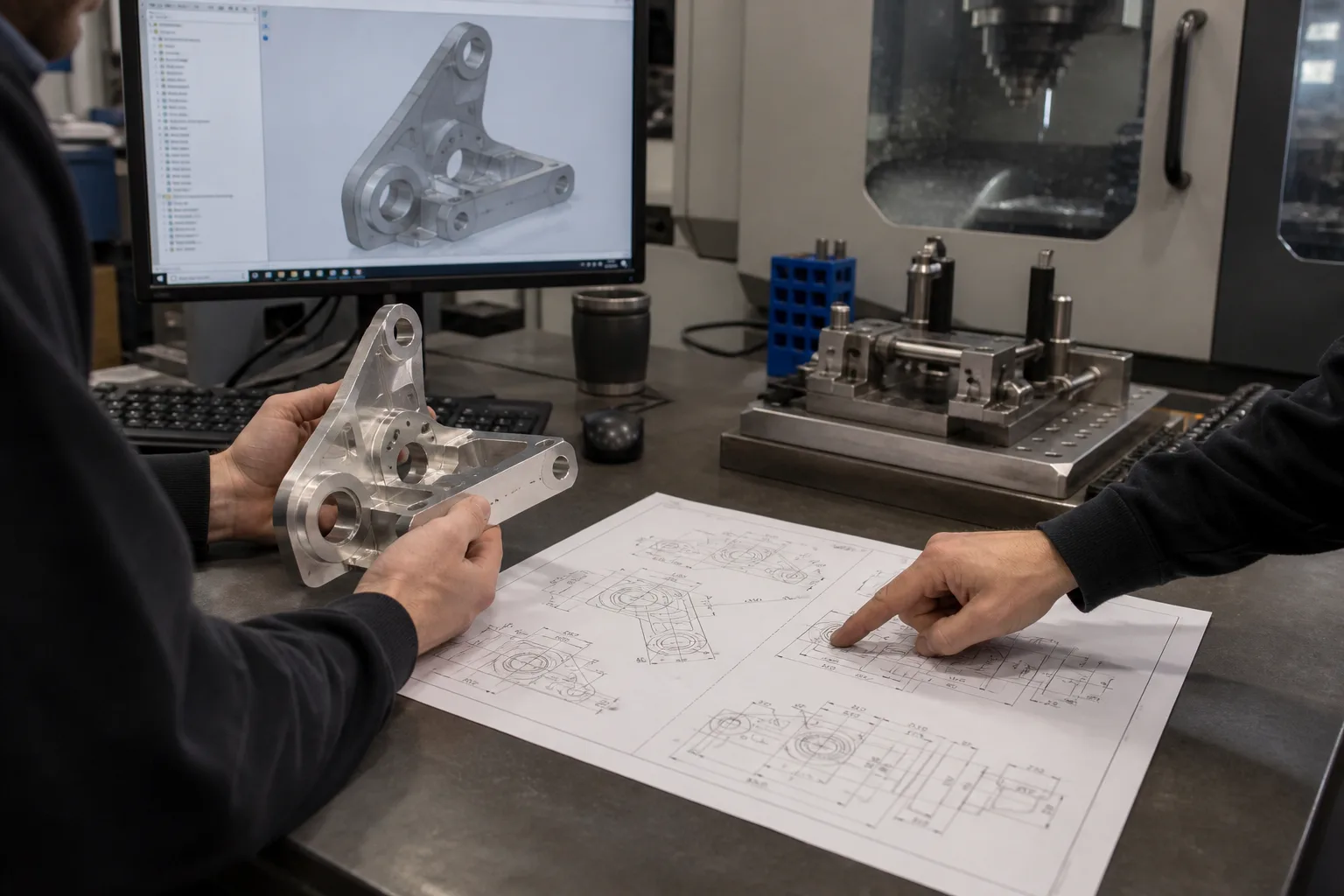
The process starts by connecting geometry, orientation and measurement—not by assuming that every difficult feature needs the same five-axis strategy.
Connect cross-face features to stable datums and inspection references.
Assess tool reach, holder clearance, collision risk and required rotary orientation.
Review fixture interference, thin walls, deep cavities and deformation risk.
Define a measurement strategy for compound angles, critical features, profiles and datum relationships.
Use this summary for an initial fit check. Final strategy and setup limits are confirmed from the actual drawing.
The inspection plan follows feature relationships and the approved datum scheme. Documentation scope is confirmed during quotation.
Verify connected critical features from the approved reference structure.
Select a method that can resolve position, orientation and related datums.
Plan profile checks around the drawing definition and accessible measurement path.
Check interfaces that control assembly, alignment, sealing or load transfer.
Confirm requested dimensional documentation and release criteria by project.
Confirmed inspection equipment: CMM, Height Gauge, Micrometer and Caliper.
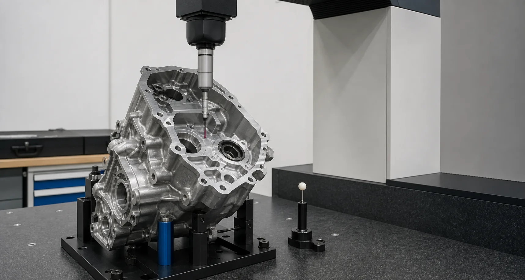
A concise route keeps geometry, datum, tool access and inspection decisions connected to the approved project requirements.
Send the 3D model, controlled drawing and project requirements.
Review geometry, datum, tool access, fixture, collision, tolerance and inspection planning.
Release the approved positioning or coordinated-motion strategy with process control.
Verify critical feature relationships and required documentation.
Package inspected complex parts against the approved release and shipment requirements.
Four drawing checks make orientation, datum and access requirements easier to review.
Show restricted surfaces, cavity depth and opening geometry in the complete 3D model.
Define functional references that can connect machining and inspection across several faces.
Identify flexible regions so stock support, clamping and cutting sequence can be assessed.
Dimension angled features from stable datums and identify only functionally critical surfaces.
Use these page sections while dedicated long-form guides are being prepared.
Review access, datums, thin walls, deep cavities, compound angles and surface requirements.
Open design guidance →Understand when fixed rotary positioning differs from continuously coordinated tool motion.
Compare strategies →Connect tool reach, holder clearance, fixture interference and collision planning.
Review engineering checks →Direct answers for engineering and purchasing teams evaluating complex multi-side parts.
Indexed 3+2 machining positions the rotary axes and then cuts with those axes held at a fixed angle. Simultaneous machining coordinates rotary and linear axes during the cut. HongKe CNC reviews the geometry, surface path, datum relationships and available machining route before selecting a strategy.
No. Some parts are more stable or economical with conventional CNC milling and planned re-clamping. The decision depends on geometry, datum relationships, tool access, tolerances and surface requirements.
Parts with compound-angle holes, related features on several faces, deep or restricted access, complex contours and setup-sensitive datum relationships are strong candidates for a 5-axis review.
The engineering review considers cutter reach, toolholder clearance, fixture interference, rotary travel, workpiece orientation and safe approach paths before the machining route is released.
Inspection planning connects the approved datum scheme to hole position, angled surfaces, profiles and mating faces. CMM, Height Gauge, Micrometer and Caliper are selected according to the feature and documentation requirement.
Send the complete 3D model and dimensioned drawing with material, quantity, critical tolerances, datum references, surface requirements, inspection needs and delivery destination. HongKe CNC then confirms the practical machining and inspection route.
The quotation form accepts DWG, DXF, STEP, STP, STL, IGES, IGS, PDF and ZIP files up to 20 MB. A 3D model plus a controlled drawing provides the clearest basis for geometry and tolerance review.
Send your CAD model and drawing. We will review geometry, datum relationships, tool access, critical tolerances and machining strategy before quotation.
Geometry, datums and critical features are reviewed.
We assess whether conventional, 3+2 or simultaneous 5-axis machining is appropriate.
You receive quotation feedback and any technical questions that require confirmation.