
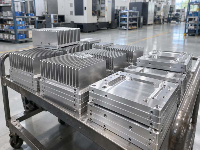
Aluminum is one of the most widely used materials in CNC machining due to its excellent machinability, lightweight properties, and natural corrosion resistance. Whether you are designing a heat sink enclosure, a structural bracket, or a complex manifold, understanding how to optimize your design for aluminum machining can significantly reduce costs, improve lead times, and ensure part quality. This comprehensive guide walks you through the key aspects of CNC machining aluminum, covering material selection, design for manufacturability, tolerances, surface finishes, and quality inspection practices.
Choosing the Right Aluminum Alloy
The first step in a successful aluminum CNC project is selecting the appropriate alloy. Each alloy offers a unique balance of strength, machinability, weldability, and corrosion resistance. Below are the most common choices for CNC machining:
6061 Aluminum
6061 is the workhorse of aluminum machining. It offers good strength (yield ~40 ksi), excellent corrosion resistance, and superior machinability. It is ideal for structural parts, brackets, enclosures, and fixtures. Post-machining heat treatments (T6 temper) can further enhance mechanical properties.
7075 Aluminum
7075 is an aerospace-grade alloy with very high strength (yield ~73 ksi), comparable to many steels. It is more difficult to machine than 6061 and tends to produce tighter chips. Use 7075 for high-stress components such as aircraft brackets, gear housings, and mold bases. Note that 7075 has lower corrosion resistance and is often anodized or coated.
2024 Aluminum
2024 alloy offers high strength and excellent fatigue resistance, commonly used in aerospace panels and structural parts. However, its machinability is moderate, and it may require sharp tools and proper coolant. 2024 is not recommended for welding but performs well in riveted assemblies.
5083 & 6082
5083 is known for its excellent marine corrosion resistance and is often used in ship components. 6082 is a European standard with strength similar to 6061, used extensively in automotive and railway applications. Both are readily machinable.
Design Considerations for CNC Machining Aluminum
Designing parts for aluminum CNC machining requires attention to geometry, tool access, and material behavior. Good design for manufacturability (DFM) can prevent costly revisions and delays.
Wall Thickness
Avoid overly thin walls. For vertical walls in pockets, a minimum thickness of 0.8 mm (0.03 in) is recommended, though 1.5 mm (0.06 in) is safer for larger parts. Thin walls vibrate, leading to chatter and poor surface finish. If thin features are unavoidable, consider adding ribs or increasing the thickness in critical areas.
Internal Corners and Radii
Sharp internal corners cannot be machined with a rotating end mill; the tool leaves a radius equal to its diameter. To avoid costly rework, design internal corners with a radius larger than the cutter radius. A general rule: use an inside corner radius of at least 0.5 times the tool diameter. For pockets, a radius of 2–3 mm (0.08–0.12 in) works well with standard tooling.
Deep Cavities and Pockets
Deep pockets (depth > 4 times the diameter) require specialized long-reach tools that are more prone to deflection. If possible, limit pocket depth to 3× tool diameter. For deeper features, consider machining from both sides or using a custom tool. Adding draft angles (0.5–1°) can aid chip evacuation and improve surface finish.
Threads and Inserts
Threads in aluminum can be machined directly with taps or thread mills. For high-strength threads or repeated assembly, use helical inserts (e.g., Helicoils) or key-locking inserts. Design the threaded hole depth at least 1.5× the nominal diameter to ensure full engagement.
Undercuts and Complex Geometries
Undercuts, T-slots, and back-drafted features often require special tooling or EDM operations. Evaluate the necessity of such features; often a simple design change can make the part completely machinable with standard 3-axis milling. Five-axis CNC machining can handle many complex shapes, but it increases cycle time and cost.
Critical Tolerances and Fits
Aluminum has a coefficient of thermal expansion (CTE) of about 23 µm/m·°C, which is roughly double that of steel. This means part dimensions can change significantly with temperature fluctuations during machining. Standard CNC machining tolerances for aluminum are typically ±0.1 mm (±0.004 in) for general dimensions, and ±0.025 mm (±0.001 in) for precision features. Tight tolerances below ±0.01 mm (±0.0004 in) are achievable but require careful fixture design, temperature control, and post-machining stabilization.
Geometric Tolerances
Flatness, parallelism, and perpendicularity should be specified on the drawing. For aluminum parts, a commercial flatness tolerance of 0.1 mm per 100 mm is typical. For high-precision applications (e.g., optical mounts), specify 0.02 mm per 100 mm. Machining stresses in the aluminum can cause warpage; stress-relieving the material before final passes helps maintain geometry.
Fits with Other Parts
For sliding fits (e.g., shaft and housing), use clearance fits such as H7/g6. For press fits, aluminum-to-aluminum requires careful sizing due to galling; a light press with Loctite or use of a steel sleeve is often preferred. Always account for the CTE mismatch with steel inserts.
Surface Finishes for Aluminum Parts
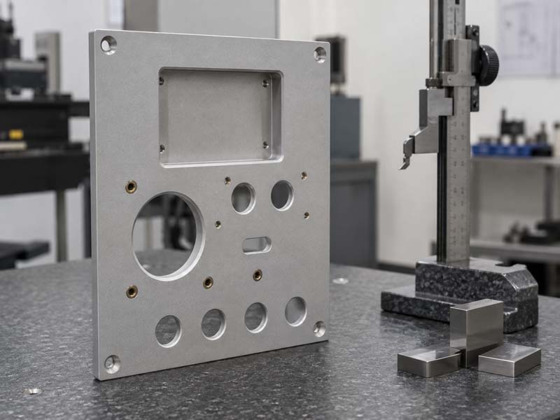
Surface finish affects both aesthetics and functional performance. The following finishes are commonly applied to CNC-machined aluminum:
As-Machined
A standard machined finish (Ra 0.8–3.2 µm) is suitable for many internal components. It is cost-effective and leaves visible tool marks. For a better appearance, specify a “fine machined” finish (Ra ≤ 0.8 µm) achieved with finishing passes and sharp tools.
Bead Blasting
Bead blasting with glass beads produces a uniform matte surface, hiding minor defects and tool marks. It is often used before anodizing. The surface roughness after blasting is typically Ra 1.6–3.2 µm. This finish does not provide significant wear or corrosion protection.
Anodizing (Type II & Type III)
Anodizing is an electrochemical process that forms a thick, hard oxide layer on the aluminum surface. Type II (sulfuric anodizing) produces a decorative layer 5–25 µm thick, available in many colors. Type III (hard anodizing) gives a thickness of 25–150 µm, with excellent wear resistance and hardness (up to 60 RC). Anodizing is the most popular finish for aluminum CNC parts due to its durability and corrosion resistance. However, it can affect tight tolerances (<0.05 µm growth per side).
Painting & Powder Coating
For custom colors and added corrosion protection, painting or powder coating can be applied. These finishes are thicker (50–200 µm) and may require masking of threaded holes. They are not as hard as anodizing but offer excellent UV and chemical resistance.
Electroless Nickel Plating
This finish provides a uniform nickel coating, offering high corrosion resistance and a low friction coefficient. It is often used for parts that must be conductive or require a uniform thickness on complex geometries.
Quality Inspection and Assurance
To ensure that your aluminum parts meet specifications, a combination of in-process and final inspection methods is used. Common techniques include:
- CMM (Coordinate Measuring Machine): Highly accurate (micron-level) inspection of 3D geometries and GD&T.
- Height Gauge and Micrometers: For quick verification of key dimensions like thickness, diameter, and depth.
- Surface Roughness Tester: To confirm Ra values match the required finish.
- Visual and Leak Testing: For manifold blocks and sealed components.
- Material Certification: Verification of alloy composition (e.g., 6061-T6) through mill certificates.
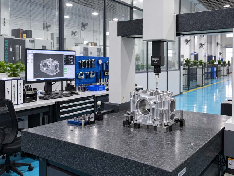
Partnering with a CNC shop that has robust quality systems—such as ISO 9001 certification—ensures that every part is checked and documented. Hongke CNC, for instance, uses advanced CMM probes and height gauges to verify critical dimensions on every batch.
Conclusion
Aluminum remains the material of choice for countless CNC machined components across industries—aerospace, automotive, electronics, medical devices, and more. By understanding the nuances of alloy selection, designing with machining in mind, specifying realistic tolerances, and choosing the right surface finish, you can achieve optimal performance and cost efficiency. Work closely with your CNC partner from the design phase to fully leverage their expertise in aluminum machining. Hongke CNC offers end-to-end support for aluminum projects, from DFM feedback to precision manufacturing and inspection, helping you bring your parts to life with confidence.