Introduction
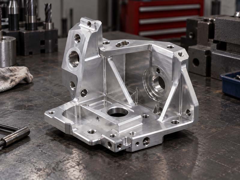
Aluminum is the workhorse of CNC machining. Its unique combination of light weight, good strength, corrosion resistance, and excellent machinability makes it the first choice for countless industries – from aerospace brackets to automotive housings, electronics enclosures, and medical devices. However, achieving the best results requires understanding how aluminum behaves during milling, turning, and drilling, and how design decisions influence cost, quality, and lead time. This guide covers everything you need to know about CNC machining aluminum parts, including material selection, design for machinability, tolerances, surface finishes, and inspection practices.
Why Aluminum Is So Popular in CNC Machining
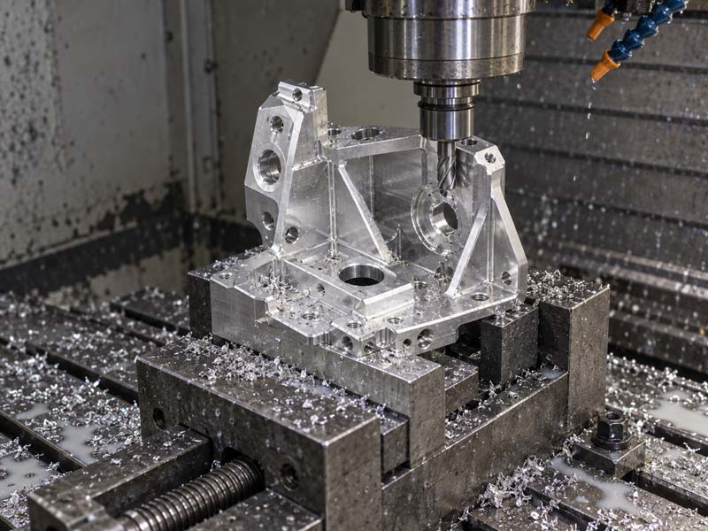
Aluminum offers a balance of properties that few other metals can match. It is about one-third the density of steel, yet certain alloys (e.g., 7075-T6) achieve tensile strengths over 570 MPa. Its thermal conductivity is high, which helps dissipate heat during cutting, reducing tool wear and improving surface finish. Aluminum also does not rust like steel; it forms a natural oxide layer that protects against corrosion. For CNC machining, the most common series are 6061 (general purpose), 7075 (high strength), 2024 (aerospace), and 5083 (marine). Each alloy has distinct machining characteristics – for instance, 7075 is more prone to burr formation, while 6061 is very forgiving.
Design for Machining (DFM) Rules for Aluminum Parts
Wall Thickness and Ribs
Aluminum is softer than steel, so thin walls can deflect or vibrate during machining. As a rule, maintain a minimum wall thickness of 0.5 mm for small parts and 1.0 mm for larger ones. When designing ribs or stiffeners, avoid sharp internal corners – use a radius of at least 1/3 of the wall thickness to reduce stress concentration and allow standard end mills to reach.
Internal Corners and Radii
Sharp internal corners cannot be machined by a rotating milling cutter. Always specify a corner radius that is larger than the tool radius. For example, if you want to use a 6 mm diameter end mill, the inside radius should be at least 3 mm. For deeper pockets, consider using larger tools to reduce cycle time. Also, avoid very deep cavities with small radii; instead, design pockets with a width-to-depth ratio of less than 4:1 to ensure good chip evacuation.
Holes and Threads
For tapped holes in aluminum, use thread depths of at least 1.5x the thread diameter for strength. Avoid blind tapped holes deeper than 3xD because chip removal becomes difficult. If you need deep threads, consider using helical inserts or thread milling. Through holes are preferred for ease of machining. For small holes below 1 mm diameter, consider EDM or laser drilling, as micro-drills are fragile.
Achievable Tolerances in Aluminum CNC Machining
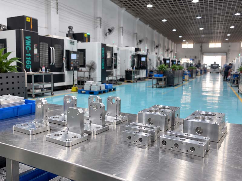
CNC machines can hold tight tolerances in aluminum, but the achievable precision depends on part geometry, machine condition, and fixturing. Standard machining tolerances for aluminum are typically ±0.1 mm (ISO 2768-m). With careful setup and good quality machines, tolerances of ±0.025 mm (0.001 inch) are possible. For features like bore diameters or critical mating surfaces, we recommend specifying an ISO tolerance class such as H7 (e.g., for a 10 mm hole, H7 gives +0.015/0 mm). Keep in mind that aluminum expands more than steel with temperature changes – a temperature variation of 10°C can change a 100 mm dimension by about 0.023 mm. Therefore, tight tolerances require temperature-controlled environments.
Reducing Tolerance Cost
Tighter tolerances increase machining time because they require multiple finishing passes, slower feeds, and possibly secondary operations. For cast aluminum (such as A356), tight tolerances are harder to achieve because internal porosity can cause uneven cutting. Whenever possible, relax tolerances for non-critical features. For large flat surfaces, specify flatness tolerances separately rather than relying on general tolerances.
Surface Finishes for Aluminum Parts
Aluminum parts can be machined to a smooth surface finish as low as Ra 0.4 μm with proper finishing passes. More commonly, standard machining gives Ra 1.6–3.2 μm. For cosmetic or seal surfaces, we often recommend Ra 0.8 μm. The finish can be further improved by:
- As-machined: Suitable for functional surfaces; visible tool marks may remain.
- Bead blasting: Produces a uniform matte texture; hides minor scratches.
- Anodizing: Adds a hard oxide layer (Type II or Type III). Anodizing is non-conductive and can be dyed in various colors. Must be specified before machining because it slightly changes dimensions (growth of about 0.025 mm per surface).
- Chemical conversion coating (Alodine): Provides corrosion protection with minimal dimensional change; often used for electrical grounding.
- Powder coating: Thicker coating for appearance and durability; not suitable for tight tolerances.
Inspection and Quality Control
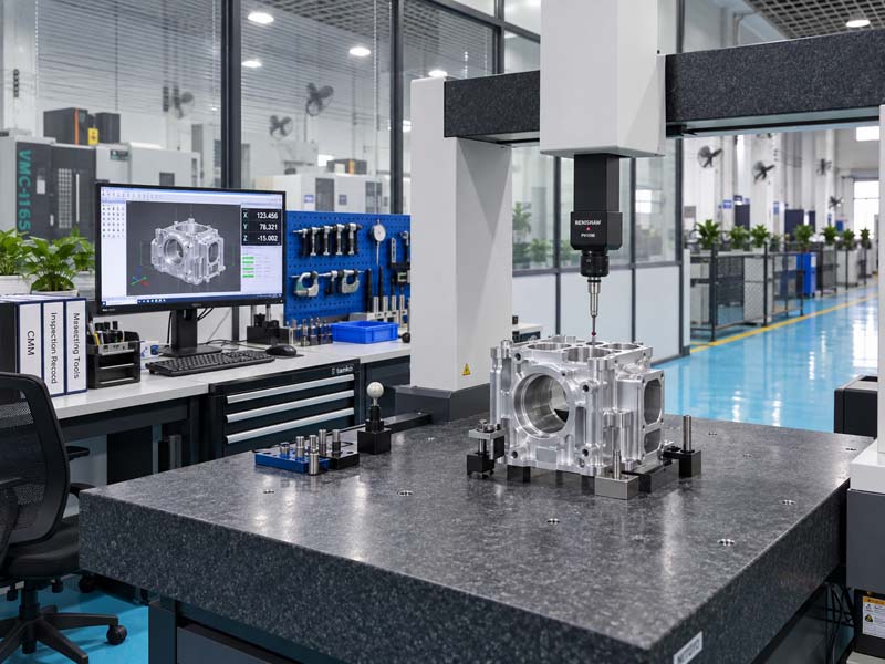
Verifying that machined aluminum parts meet specifications requires appropriate inspection tools. For dimensional checks, calipers and micrometers are used for simple features, but coordinate measuring machines (CMM) are preferred for complex geometries. Surface roughness is measured with a profilometer. Thread gauges ensure tapped holes are within tolerance. For high-volume production, we recommend statistical process control (SPC) with regular sampling.
When anodizing is specified, the coating thickness should be measured with an eddy current gauge. Also, check for warpage after anodizing, especially on thin-walled parts. For critical aerospace parts, non-destructive testing such as X-ray or ultrasonic inspection may be required to detect internal voids.
Common Challenges and Solutions
- Buildup edge (BUE): Aluminum tends to weld to the cutting edge at low speeds. Use sharp tools, high cutting speeds, and coolant to avoid BUE.
- Burr formation: Especially on 7075 aluminum. Use climb milling, sharp tools, and deburring passes. For small holes, use a back deburring tool.
- Vibration/chatter: Caused by thin walls or long unsupported tools. Reduce stepover, use rigid fixturing, and try variable-pitch end mills.
- Heat distortion: Thin aluminum parts can warp due to residual stress. Stress-relieve the stock before machining or use rough and finish cycles with cool-down periods.
Choosing the Right CNC Machining Partner
Not all CNC shops have the same experience with aluminum. Look for a partner that understands the nuances of different alloys, offers in-house inspection (CMM, surface roughness, thread gauges), and provides design feedback to optimize your part for manufacturability. At Hongke CNC, we specialize in high-precision aluminum machining with 3-axis, 4-axis, and 5-axis capabilities, and we routinely achieve tolerances of ±0.01 mm on critical features.
Conclusion
Aluminum remains the most versatile and cost-effective material for CNC machined parts. By applying sound design-for-machining principles, specifying realistic tolerances, and choosing the appropriate surface finish, you can achieve high-quality components that meet your functional and aesthetic requirements. Understanding the material's behavior during cutting and finishing will help you avoid costly mistakes and lead to faster production cycles. Whether you are prototyping a new product or ramping up mass production, aluminum CNC machining offers the speed, precision, and reliability that modern manufacturing demands.