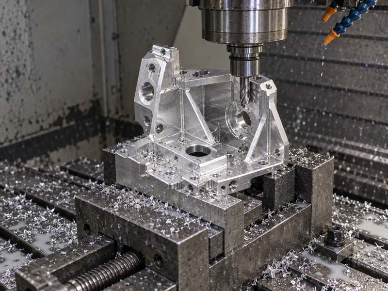
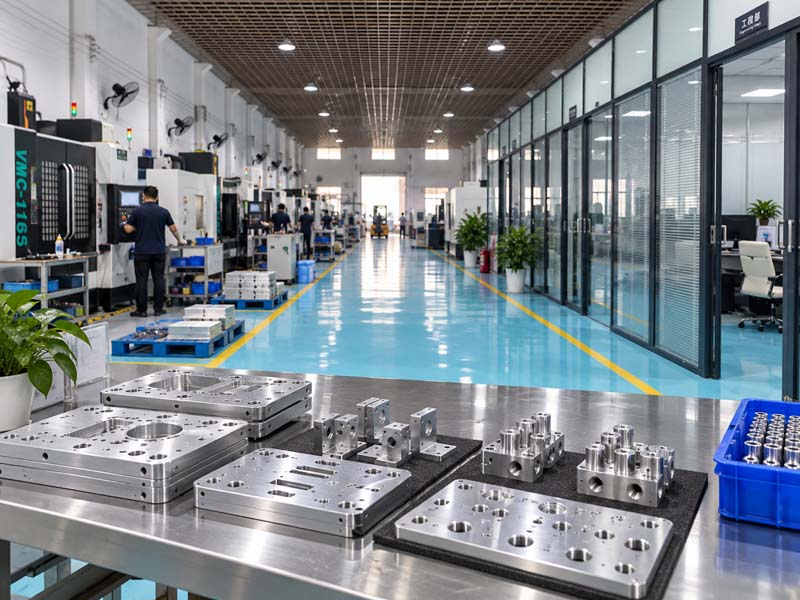
Introduction: Why Design for CNC Machining Matters
CNC machining is one of the most versatile and widely used manufacturing processes for producing high-precision metal and plastic parts. However, not every part designed in CAD is equally easy or cost-effective to machine. Understanding the fundamentals of design for machining can significantly reduce production costs, lead times, and scrap rates while improving part quality. This guide provides practical advice for engineers and product designers to create CNC-friendly designs that perform exactly as intended.
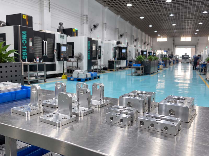
Key Design Considerations for CNC Machining
1. Wall Thickness and Feature Size
Avoid overly thin walls that can deflect during cutting or vibrate excessively. For metal parts (e.g., aluminum 6061), a minimum wall thickness of 0.8 mm (0.030 in) is recommended, though 1.5 mm or more is safer for rigidity. For plastics, thicker walls (≥1.5 mm) help prevent melting or deformation. Thin features such as narrow slots should have a width at least 2–3 times the depth to avoid tool breakage.
2. Internal Corner Radii
Sharp internal corners are impossible to machine with a rotating tool. Always design internal fillets (radius) that match a standard end mill diameter. A general rule: use a radius of at least 1/3 of the cavity depth. Larger radii allow larger tools, faster machining, and better surface finish. Avoid square corners unless they are at the top surface only.
3. Avoid Deep Cavities and Pockets
Deep pockets require long tools that deflect and leave poor finishes. Limit pocket depth to 4× the cutter diameter for optimal results. If deeper pockets are necessary, consider designing with variable depths or stepped walls to allow shorter tools. Alternatively, use drilled and tapped holes at the bottom to reduce depth requirements.
4. Threads and Tapped Holes
Standard thread sizes (M3, M4, M5, M6, etc.) are readily machined. Avoid very fine threads (#0-80) or extremely coarse threads unless necessary. Provide sufficient thread length: for through holes, 2–3 times the diameter; for blind holes, add extra depth for the tap lead. Avoid blind holes with a flat bottom; specify a standard drill point angle (118° or 135°).
5. Undercuts
Undercuts (features that cannot be reached from the top or bottom) require special tools or additional setups, increasing cost. Simplify designs to use standard end mills whenever possible. If undercuts are unavoidable, design them with a straight wall and a radius that matches a lollipop cutter or a T-slot cutter.
Material Selection for CNC Machining
The choice of material greatly affects machinability, cost, and part properties. Here is a quick comparison of common materials:
- Aluminum 6061-T6 – Excellent machinability, good strength, corrosion resistant. Ideal for most structural parts.
- Aluminum 7075 – Higher strength but slightly more abrasive; suitable for aerospace and high-stress components.
- Stainless Steel 304/316 – Tough, gummy in machining; needs sharp tools and slower feeds. Use 303 for better machinability.
- Brass – Very easy to machine, excellent surface finish, good for precision fittings and decorative parts.
- Engineering Plastics (Nylon, Delrin, PEEK) – Lightweight, wear-resistant; require sharp tools and careful heat management.
Consult with your machining partner to select the optimal material for your application and budget. Many shops stock common alloys to reduce lead time.
Tolerances and Inspection
Typical CNC machining tolerances: ±0.1 mm (standard), ±0.05 mm (precision), and ±0.025 mm (high precision). Do not specify tighter tolerances than necessary, as each extra micron increases cost exponentially. Features such as bores, mounting surfaces, and critical mating dimensions should be toleranced; non-critical dimensions can use general tolerances (e.g., ISO 2768-m).
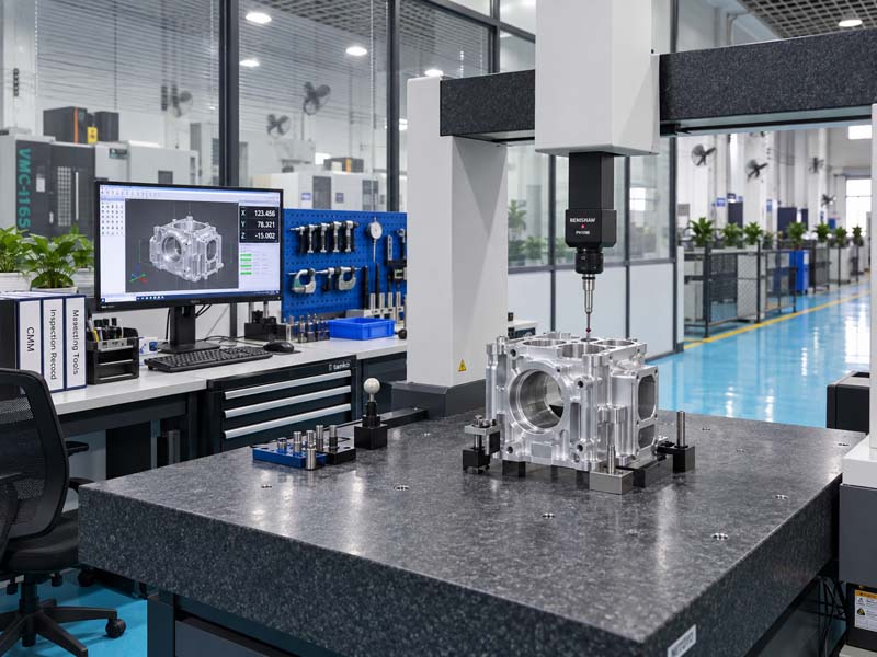
Inspection methods include calipers, micrometers, CMM (coordinate measuring machine), and go/no-go gauges. For large production runs, statistical process control (SPC) ensures consistency.
Surface Finishes for CNC Parts
The default as-machined finish shows visible tool marks (Ra 3.2–1.6 µm). For improved appearance or functional requirements, specify one of these finishes:
- Bead Blasting – Produces a uniform matte texture; hides machine marks.
- Anodizing (Type II or III) – Adds hard, wear-resistant coating; available in colors. Only for aluminum.
- Powder Coating – Thick, durable finish for steel or aluminum.
- Electropolishing – Improves smoothness and corrosion resistance on stainless steel.
- Brushed Finish – Linear grain appearance; often used on enclosures.
Remember that post-processing adds cost and time; include it in your budget if appearance is critical.
Common Design Mistakes and How to Avoid Them
Mistake 1: Over-tolerancing everything
Only critical dimensions need tight tolerances. Apply general tolerances to the rest. Use GD&T for functional features.
Mistake 2: Deep threads in blind holes without sufficient bottom clearance
Always leave 1–2 thread pitches extra depth below the full thread to accommodate the tap chamfer.
Mistake 3: Designing features that require custom tooling
Standard end mills come in diameters like 1/8", 3/16", 1/4", 3/8", 1/2". Design internal radii to match these diameters. Avoid odd sizes like 0.156" radius unless necessary.
Mistake 4: Ignoring tool access
All features must be reachable by the cutter. Deep, narrow slots with a bottom radius need a cutter that can fit. Consider 5-axis machining for complex parts, but that raises cost.
Conclusion
Designing for CNC machining is about balancing functionality with manufacturability. By following the guidelines above—optimizing wall thickness, using proper radii, selecting appropriate materials, and specifying realistic tolerances—you can achieve high-quality parts at competitive prices. Collaborate with your CNC service provider early in the design phase to identify potential issues and streamline production. For more detailed advice on specific materials or processes, explore our Technical Guides.