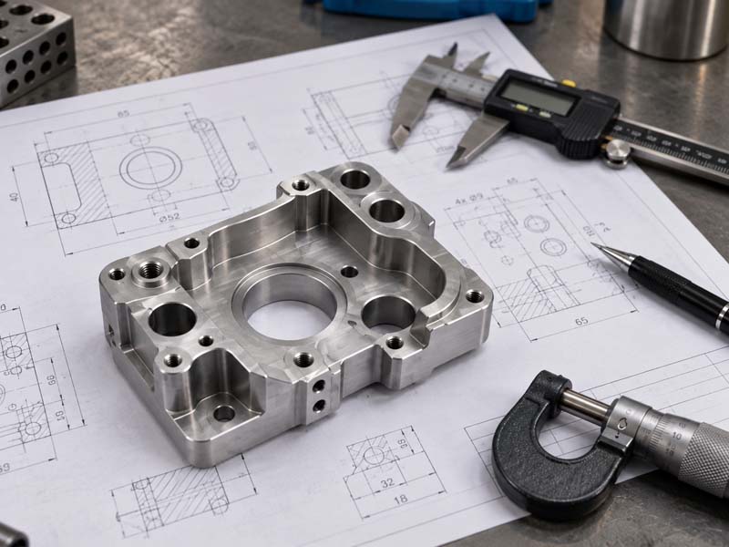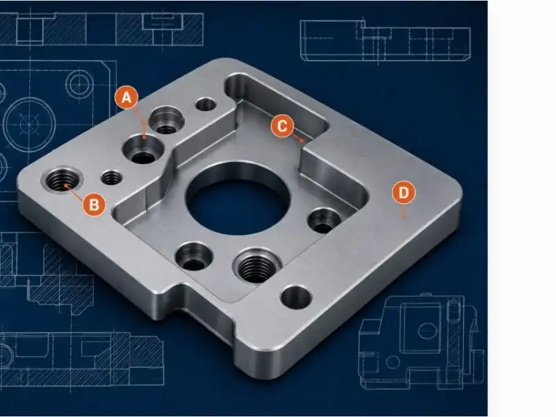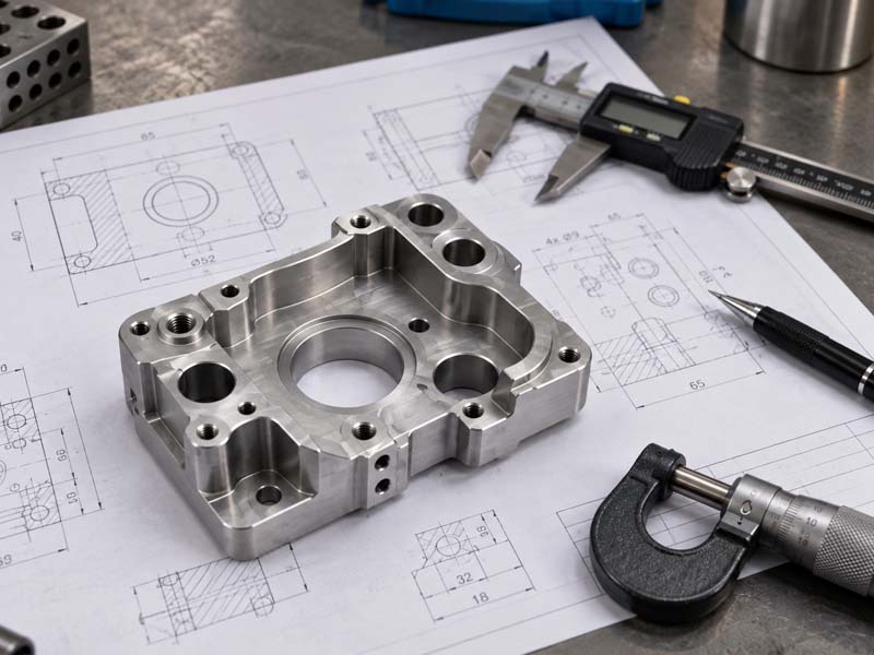
A datum is the physical feature you agree to measure from. Choose it carelessly and the drawing describes one part while the shop builds and inspects another. The dimensions can all be correct while the part is still wrong.
Quick Answer
Pick the primary datum as the largest stable surface that seats on a fixture and survives machining. Add a secondary datum to stop rotation in that plane, then a tertiary datum for the last movement. The stack should follow the 3-2-1 principle: three points on the primary, two on the secondary, one on the tertiary. Each datum should be real, accessible, and inspectable.
Key Takeaways
- A datum is a reference, not a dimension: it defines where measurement begins, not how large a feature must be.
- The primary datum is typically the largest, flattest, most stable face that seats naturally on a fixture.
- The 3-2-1 principle removes all six degrees of freedom.
- Datum features must be reachable by both the fixture and the probe.
- A legacy scheme may not suit a new process, so review it when a part changes supplier.
What a Datum Actually Controls
A datum does not state how big a feature is. It states where zero is.
Once declared, every dimension and geometric tolerance referring to it is measured from that plane, axis, or point. Change the datum and the same tolerance governs a different physical relationship. Two drawings can carry identical tolerance blocks and still produce incompatible parts purely because the datums differ.
Datum selection therefore sits upstream of tolerance selection. Decide how the part will be located, then how tightly each feature must be held.
Three terms are worth keeping straight. A datum is the theoretical reference: a plane, axis, or point. A datum feature is the real surface that establishes it. A datum reference frame is the combination of datums forming the coordinate system for inspection.
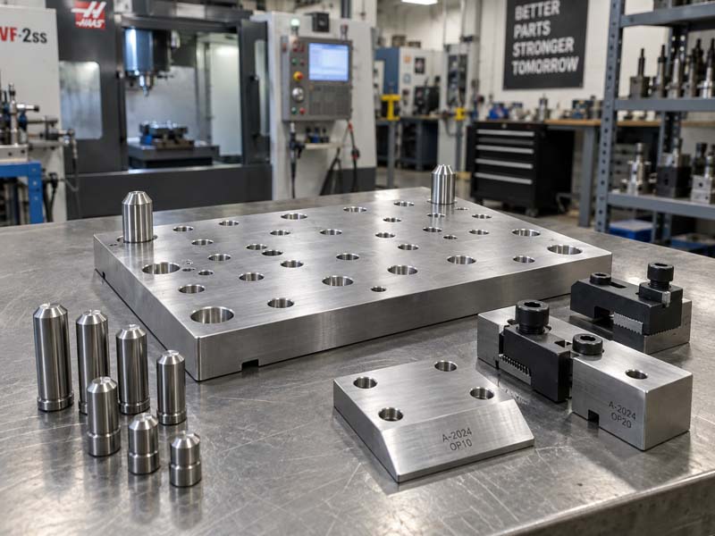
A well-chosen primary datum matches the surface a fixture can genuinely seat.
Applying the 3-2-1 Principle
The 3-2-1 principle is the useful starting point for a rigid, prismatic part.
Rest the part on three points of the primary datum. That removes translation along one axis and rotation about two others. Two points on the secondary datum fix rotation about the remaining axis. A single point on the tertiary datum removes the final translation.
The three primary contact points should sit as far apart as the geometry allows, because widely spaced contacts resist rocking far better than a cluster near the centre.
Typical practice on a machined housing is to use the mounting face as the primary datum, a pair of dowel holes or a long machined edge as the secondary, and one hole or edge feature as the tertiary. Where a part is not prismatic, or thin walls make seating unreliable, the assumption can break down, so a manufacturing engineer should confirm the scheme against the actual part. CNC machining tolerances sets out what different processes can realistically hold.
Choosing the Primary Datum
The primary datum carries the most weight, so it deserves the most scrutiny. Three questions narrow the choice.
Can the part sit on it? It should seat without rocking. A rough cast surface with draft and flash is a poor candidate unless it is machined first.
Will it survive the process? A thin flange that may distort, or a surface blended during deburring, may not hold its shape by inspection time.
Can the shop reach it? The primary datum has to be presented to the fixture across operations, and a face buried after the first setup cannot be maintained later.
A smaller machined pad that seats cleanly often outperforms a larger surface that rocks.
The secondary datum fixes rotational position, so it needs length: two dowel holes used together define an axis, and a long machined edge works as well. A short edge beside a corner is a poor option, because angular uncertainty is large relative to feature length. The tertiary datum removes the last degree of freedom and is chosen for clarity rather than strength.
Datums and Inspection
A datum scheme is only workable if it can be reproduced away from the machine.
Inspection equipment establishes datum features in a defined order. A coordinate measuring machine seats the part, acquires the primary, then the secondary, then the tertiary, and reports every characteristic relative to that frame. If the primary datum cannot be presented to the machine's table, the inspector has to improvise, and improvised references produce measurements the shop cannot defend.
Datum selection also interacts with surface condition: a datum face polished or coated after machining may no longer represent the surface the tolerances were calculated against. How to Prepare a 2D Drawing for CNC Machining covers the drawing conventions that keep this ambiguity off the shop floor.
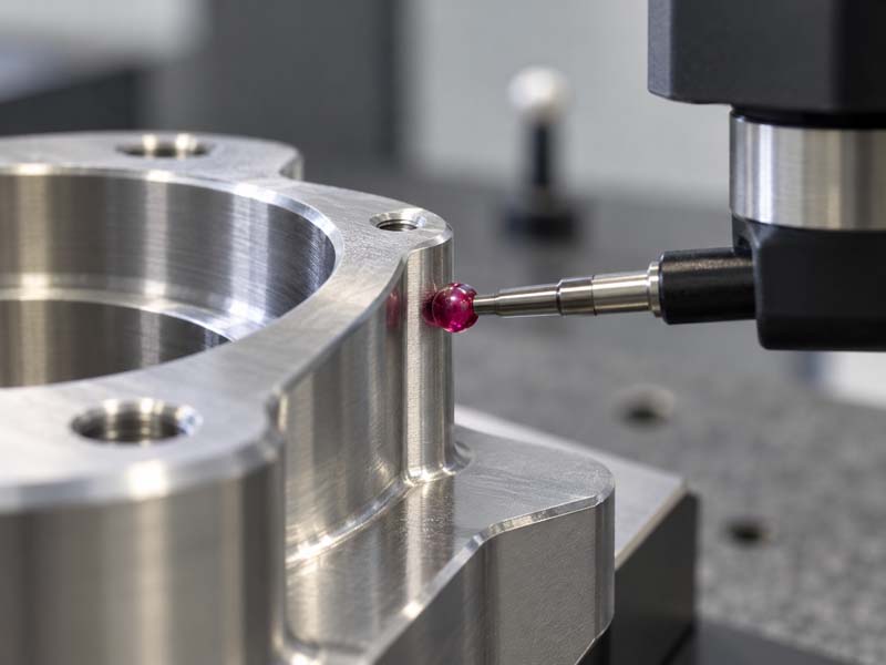
On a CMM or a surface plate the datum features are established in the order declared on the drawing.
Common Mistakes
Using a non-machined surface as a primary datum. Cast and forged surfaces carry draft and scale variation, so unless machined first they cannot locate the part repeatably.
Changing the scheme between machining and inspection. If the shop holds the part on one face and inspection seats it on another, a tolerance met in one frame may fail in the other.
Nominating a datum without checking access. A datum feature must be reachable by the fixture and the probe, or it causes drawing rework when the machine cannot hold it.
FAQ
Does every dimension need a datum reference?
No. Plain dimensions such as overall length do not require one. Datum references matter for geometric tolerances such as position, profile, and perpendicularity, where measurement needs an unambiguous origin.
Can a hole be a primary datum?
Yes, when the axis is the controlling reference. A bore that is the functional centre of a part is often declared as the primary datum. The choice follows function, not shape.
Practical Summary
Datum selection decides how a part is located on the machine, in the fixture, and on the inspection table. Choose a stable primary surface that seats cleanly and survives the process, add a secondary datum long enough to define a direction, and finish with a tertiary feature that removes the last ambiguity. Keep the sequence consistent between machining and inspection, and revisit the scheme whenever a part changes process or supplier.