Quick Answer
Choose tolerances by function, then make the datum scheme and inspection method visible on the drawing. A tight value without a functional reason usually adds cost without improving the part.
Key Takeaways
- Apply the tightest limits only to features that control fit, sealing, motion, alignment or appearance.
- Define datums from the surfaces that actually locate the part in its assembly.
- Match the callout to a practical inspection method before releasing the drawing.
- State whether acceptance applies before or after finishing and with the part free or supported.
A machine's positioning specification does not tell you whether a finished bore will fit its mating part. The material, feature shape, setup and inspection method all affect that result. Start with the assembly relationship you need to protect, then work out how to make and measure it.
Separate ordinary dimensions from functional controls
A general tolerance covers dimensions that do not need an individual limit. It is still an acceptance requirement, not permission to ignore size. A tight tolerance deserves its own functional reason: a locating diameter, a sealing face, a sliding interface or the relationship between mounting holes. Define the reference surfaces that make the requirement meaningful.
Putting ±0.02 mm on every dimension can impose close control on edges that never touch another component. It can also leave the truly important relationship uncontrolled: two accurately sized holes may still be in the wrong positions. Review size, position, orientation and form as separate design questions rather than treating a smaller plus/minus value as a universal improvement.
Why the same number can describe different manufacturing problems
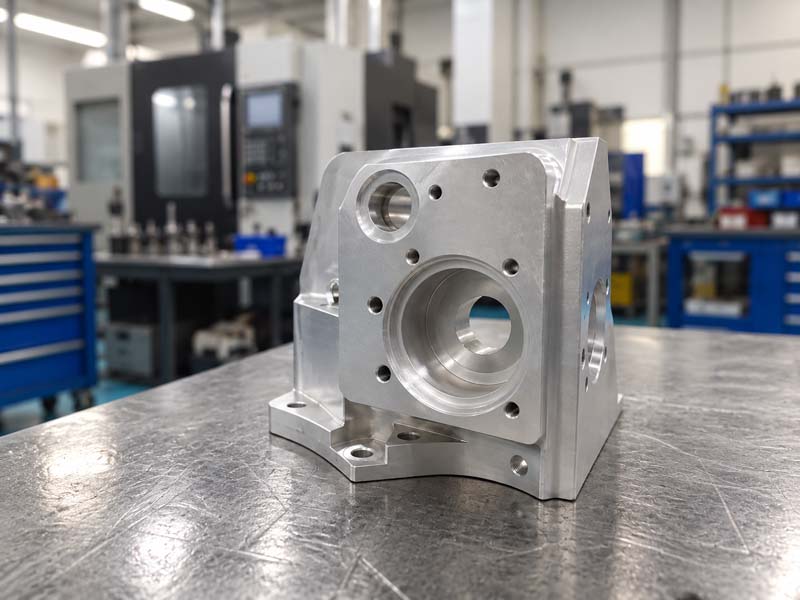
A short accessible bore in a stiff part is a different job from a deep bore behind a thin wall. Tool reach, heat, cutting forces and workholding can affect the result. Features completed in different setups also need a repeatable relationship to the chosen datums. More machine axes can improve access, but do not remove these sources of variation.
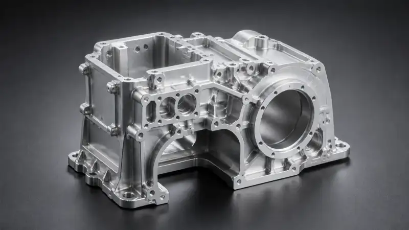
Material condition matters alongside the grade. Removing stock may release residual stress; heat generated during cutting can change a measurement taken before the part stabilizes. Finishing can alter a size or edge. Specify whether acceptance applies before or after the final treatment, and discuss supporting or restraining a flexible part during inspection.
Match the control to the consequence
| Feature | Functional requirement | Capability factors | Inspection consideration |
|---|---|---|---|
| Bearing location | Maintain shaft alignment and the intended fit | Bore depth, wall support, stock condition and datum transfer | Check size and the required axis relationship to assembly datums |
| Mounting clearance | Allow assembly without unwanted movement | Hole access, pattern position and number of setups | Verify the pattern against its locating surfaces and fastener clearance |
| Sealing face | Maintain contact and the required surface condition | Face support, tool access and final treatment | Check the specified form, texture and finished condition |
| Cosmetic edge | Meet the agreed appearance and handling requirements | Edge access, deburring and finishing | Use agreed edge and visual criteria; add close size limits only if needed |
| Input | Define on the drawing or RFQ | Why it matters |
|---|---|---|
| Dimensional limit | Nominal size, upper/lower limits and units | Defines the actual acceptance interval |
| Datum relationship | References and the controlled orientation or position | Connects the feature to assembly function |
| Material condition | Grade, condition and stock form | Supports assessment of movement during stock removal |
| Finished state | Before or after treatment; free or restrained | Prevents different interpretations of acceptance |
| Verification | Method, access, sampling and required records | Includes measurement feasibility in the quotation |
Include inspection in the feasibility decision
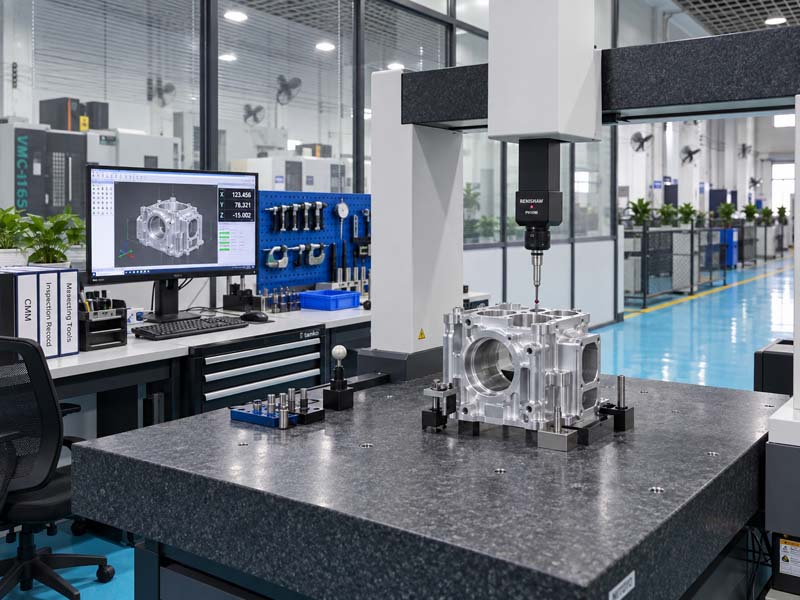
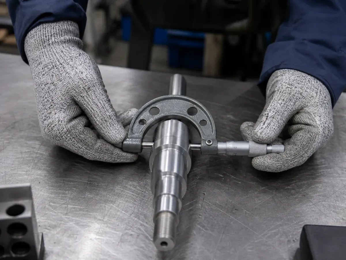
A tolerance must be paired with a method capable of evaluating the specified characteristic. Resolution alone is insufficient: access, contact geometry, datum simulation, temperature and measurement uncertainty also matter. Agree on the condition of the part and any record required before pricing repeated measurements across a batch.
Our quality and inspection page identifies available methods and project-specific review. The site's confirmed reference is down to ±0.005 mm for selected critical features after review; this is not a blanket tolerance for an entire part. A drawing-specific assessment may recommend a different process, feature redesign or acceptance method.
What This Means for Your Part
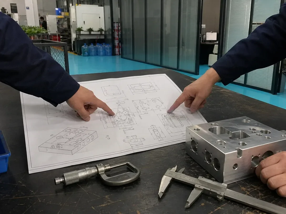
Mark the dimensions whose variation can change fit, motion, sealing or alignment. For each, provide the allowable range, datum relationship, finished state and reason for the control. Leave other dimensions under a clear general rule approved by your design authority. Use manufacturing drawing review to reconcile those requirements with the model and proposed setups.
If you do not yet know the necessary limit, send the mating geometry and explain the failure you need to avoid. Ask for feasibility feedback before freezing an arbitrary number. Include quantity and requested measurement records in your RFQ package so that the quotation covers the acceptance work as well as cutting time.
- Mark every feature whose variation affects fit, sealing, motion or alignment.
- Show the datums that control each tolerance and the finished material condition.
- State the inspection method where a standard caliper check is not sufficient.