
Quick Answer
A profile tolerance controls how far a surface may deviate from its true profile — the exact geometry located by basic dimensions. The stated value is the total width of the profile tolerance zone, split evenly on both sides of the true profile unless the drawing says otherwise. Profile limits form, orientation and location at once, so it appears where a chain of plus-minus dimensions would be unreadable.
Key Takeaways
- The value is a total zone width: 0.2 mm means 0.1 mm each side by default.
- Basic dimensions define the true profile; without them the callout locates nothing.
- An unequally disposed profile biases the zone to one side, often on sealing faces.
- Profile of a surface covers the whole feature; profile of a line covers single cross-sections.
- Profile can replace several plus-minus dimensions plus an orientation control.
- Inspection effort scales with point count, so settle sampling before price.
What a Profile Tolerance Actually Controls
The true profile comes from a CAD model or from basic dimensions in boxes. The zone is built by offsetting that profile by half the stated value each way, and every point of the finished face must sit between the two boundary surfaces.
One statement replaces a chain of plus-minus distances whose meaning would otherwise depend on how the dimension lines are read. Profile therefore appears on parts defined by shape: impeller blades, pump housings, covers with generous blends, castings machined only on selected pads.
Datums still decide the difficulty: the same 0.3 mm band is easy or hard depending on which faces were chosen as A, B and C. The reasoning is in the guide to datum selection for CNC machining.
Bilateral, Unilateral and Unequally Disposed Profiles
The default disposition is bilateral: equal zone each side of the true profile. An unequally disposed profile shifts it, written as the U modifier plus the portion outside the true profile — 0.4 U 0.1 leaves 0.1 mm of material outside and 0.3 mm inside. Notation varies by standard edition, so read the drawing note.
Bias follows function. A sealing face that must not protrude past its mate wants the allowance inward; a coated surface wants room outside, so the band holds after plating or anodizing.
A one-sided profile is an asymmetric limit on a curved surface, with the trade-offs of unilateral and bilateral tolerancing on plain dimensions: easy to state, harder to hold.
Profile of a Surface vs Profile of a Line
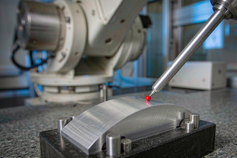
Profile of a surface treats the feature as a whole. The zone lies between two surfaces offset from the true profile, and every point on the machined face has to fall inside. It is the common version on machined parts, since it matches how a CMM evaluates a feature.
Profile of a line applies per cross-section, each with its own two-line zone, and appears where the drawing needs control slice by slice: long extrusions, rolled profiles, parts whose section shape matters more than the whole.
Reporting differs too: a surface callout gives one worst-point number, a line callout gives numbers tied to sections — useful when the process has a directional bias, such as scallops from a ball nose cutter.
Profile Tolerance or Position Tolerance
Position applies to features of size — holes, slots, pins, bosses — where one dimension defines the feature and the zone centers on its axis or center plane. For a hole pattern it is usually cheaper to verify, since a go/no-go gauge or a short CMM routine settles it. The mechanics are in the guide to specifying position tolerance for hole patterns.
Profile applies to surfaces with no size dimension of their own: a contoured rib, a blend, an irregular pocket wall, the outside of a housing.
Composite profile tolerance covers the middle case: loose location against the datums, tight control of each shape — upper segment for pattern location, lower for form and orientation.
Calling Out Profile Tolerance on a Drawing
The feature control frame sits on the surface it controls, or on a leader with the all-around symbol when the requirement wraps a closed contour. It carries the profile symbol, the total zone width, any unequally disposed modifier, and datum references in the order that builds the frame.
Basic dimensions do the locating. Box them and make sure they close the geometry, because a profile callout on a surface still dimensioned with plus-minus values is contradictory.
Do not dimension the same surface both ways, and state a non-bilateral disposition explicitly rather than in a title block note. Call out edge treatment separately: a surface ending in a sharp corner leaves that corner undefined.
Inspecting Profile Tolerance
On a CMM the surface is measured as a point set or a scan: a dense scan describes it well but takes time, a sparse set can miss a deviation between points. Count and distribution belong in the inspection plan, agreed before production, not after a rejection.
Fixturing matters as much: the part must be established on the datums named in the frame, since a convenient parallel can shift the result by more than the tolerance. Probe radius compensation is the other routine error on contoured faces.
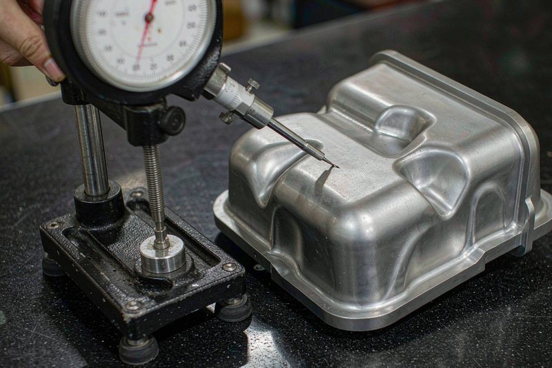
Simple methods still earn their place: a dial indicator on a surface plate confirms a shallow contour with a generous band, and hard gauges suit volume. Tighter bands are realistic on selected critical features, depending on material, geometry, workholding, process route and inspection requirements.
FAQ
Does profile tolerance control size?
Not the way a plus-minus dimension does. Profile fixes where a surface sits relative to its true profile; on a closed shape the band still limits overall size. For a feature of size, pair a size tolerance with a separate geometric control.
Can profile be used without datum references?
It can, with a different meaning: without datums the band floats relative to the part, so only form is limited.
How many points are enough to verify a profile callout?
No fixed number exists. Enough to catch what the process can produce, placed where it is weakest — on a contoured face cut with a ball nose tool, across the scallop pattern as well as along it.
Profile tolerance compresses a page of dimensions into one statement about a surface, and it pays back only when the drawing is fully defined.