Quick Answer
A projected tolerance zone extends the position tolerance of a hole or thread above the part surface for a stated height, so it describes where the mating pin lands rather than where the hole was cut. It applies to features that receive a pin, insert or stud long enough for angular error to matter, with the height dimensioned from the datum the mating part seats against. Without it, a hole that passes inspection can still build into an assembly that will not go together.
Key Takeaways
- The projected tolerance zone controls the position of the mating feature, not just the hole in the plate.
- Projection height should cover the mating part thickness plus any gap, washer or shim stack.
- The zone projects from the datum that contacts the mating part, so datum choice drives the result.
- Extending the zone above the surface raises inspection effort, so reserve it for assembly-critical features.
What a Projected Tolerance Zone Actually Controls
An ordinary position tolerance controls the hole axis within the thickness of the part — the right control when the feature only has to line up with something of similar depth.
A projected tolerance zone changes the volume being controlled: the tolerance cylinder starts at the datum surface and extends outward, away from the material, for a specified height. Extended through that height, the hole axis has to stay inside it, so the criterion describes the worst position of the pin, not the hole.
The distinction matters because a pin amplifies angular error: a hole that sits inside its position tolerance at the near face but leans pushes the pin further off center the longer the pin is. Projection captures that in one callout instead of a separate perpendicularity control.
Why Press-Fit Pins and Studs Need It
Picture a cover plate bolted to a housing through four dowel pins pressed into the housing. Each hole could sit near the edge of its tolerance in a different direction and the plate would still drop over the pins, because clearance absorbs the offset. Lean a pin, though, and its tip lands further from nominal than the hole it came out of.
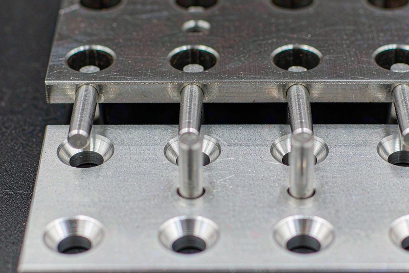
The same logic applies to threaded studs and inserts. The thread can sit well inside its position tolerance at the surface while the far end of the stud lands outside the clearance hole in the mating part. Short fasteners and generously clearanced holes rarely need projection; long studs in thin plates are where the control earns its place, and a tolerance stack-up analysis shows whether the added tip error still leaves room for assembly.
How to Apply the Modifier on a Drawing
Applying the control comes down to choosing the right reference and stating the height.
- Identify the feature that receives the mating pin, stud or insert. That feature carries the modifier, not the clearance hole in the mating part.
- Select the datum the mating part seats against — often the opposite face from the one the hole was drilled from. Choosing the drilling face projects the zone into thin air.
- Add the modifier to the position tolerance frame beside the tolerance value, and keep the datum reference frame consistent across the pattern; the datum selection guide covers how to avoid over-constraining the part.
- Dimension the projection height from that datum. A note such as "project 12 mm from datum A" removes argument during first article review.
Choosing the Projection Height and Material Condition
The projection height should represent the highest point the mating feature reaches above the datum: mating part thickness plus any gap, washer or shim stack. Projecting further adds cost without benefit; projecting less leaves the risk in place.
Material condition modifiers interact with projection. Where the feature is a clearance hole and assembly depends on hole size, a maximum material condition modifier is often combined with the projected zone, so bonus tolerance applies to the projected cylinder; the governing GD&T standard defines that combination.
Not every hole needs it. Applying the control to the two locating holes and leaving the rest under an ordinary position tolerance is common practice, and those holes follow the same hole tolerances and fits logic as the rest of the part.
Inspecting a Projected Tolerance Zone
A coordinate measuring machine can handle the control directly: measure the hole at two heights, derive the axis, extend it to the projection height and compare with the tolerance cylinder. That needs a straight bore and a datum setup matching the drawing intent.
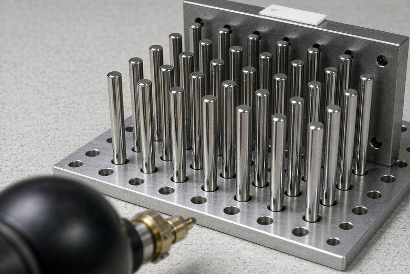
Functional gaging is faster in production. A gage pin sized to the virtual condition and long enough to reach the projection height is passed through a gage plate representing the datum; if it enters, the projected zone is satisfied. The guide to position tolerance for hole patterns covers the same idea.
Common Mistakes When Specifying Projection
- Leaving the projection height off the callout. The modifier alone says the axis matters above the surface but not how far, so the requirement cannot be inspected as written.
- Projecting from the drilling face instead of the mating face. The zone then describes a volume the pin never occupies, and a conforming part may still fail to assemble.
- Ignoring coating thickness. Plating and other supplier-coordinated finishing steps shift the surface the mating part rests on, which changes the height the pin actually reaches.
FAQ
Does a projected tolerance zone change the hole's own tolerance?
No. The size and position tolerances at the surface stay as written. What changes is the volume in which the axis must remain, and it extends beyond the part.
How is it different from perpendicularity?
Perpendicularity limits how far the axis tilts relative to a datum; projection limits where it ends up at a specific height, folding tilt and offset into one condition.
Should the control go on a clearance hole or a threaded hole?
Either can carry it. A threaded hole or insert is the more common case, because stud length is fixed and tip error is easy to visualize. What is attainable on a specific feature depends on material, geometry, workholding, process route and inspection requirements.