Quick Answer
Use turning when the dominant features are coaxial to one centerline. Use milling for prismatic forms, pockets and multi-face features; use both when the geometry needs both strengths.
Key Takeaways
- Start with the part’s primary geometry and datum axis, not the material.
- Avoid forcing turned details into a milled blank when concentricity drives the function.
- Plan secondary operations only after the base process makes the critical geometry stable.
A shaft with wrench flats still has a main axis to preserve. A mounting block with a bore still needs its faces and hole pattern to align. Secondary features can add operations without changing the best starting process; plan the route around the relationships that matter in assembly.
Look for the natural reference geometry
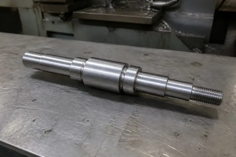
In turning, the workpiece rotates and the tool generates features around that rotation. External diameters, bores, shoulders and axial grooves often fit this arrangement. If several diameters must relate closely to one another, completing them in a suitable common setup can simplify that relationship.
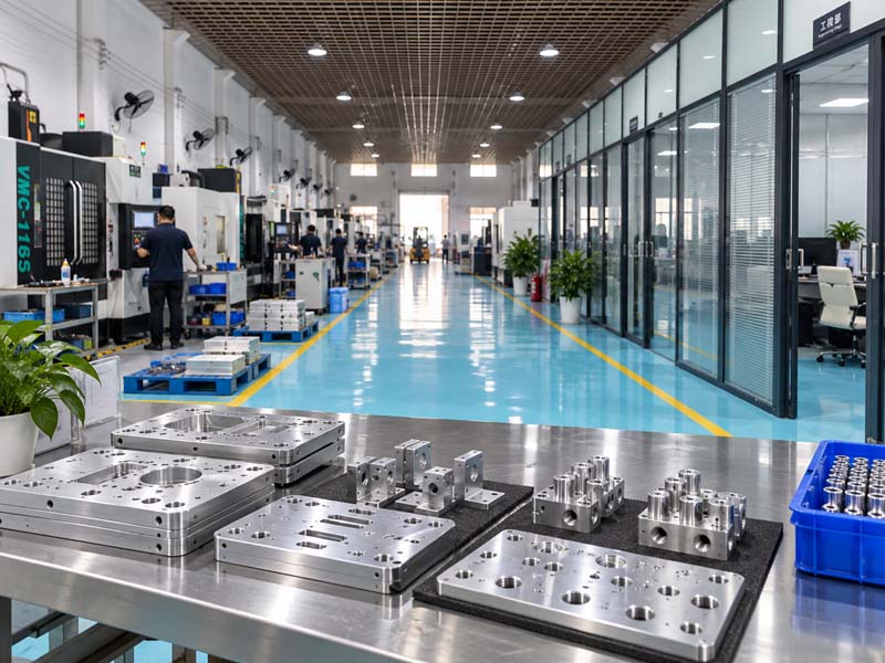
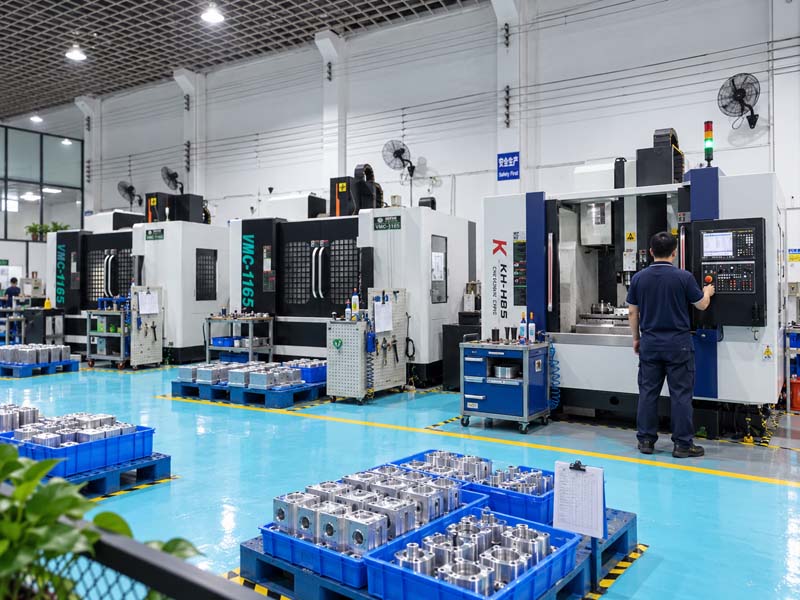
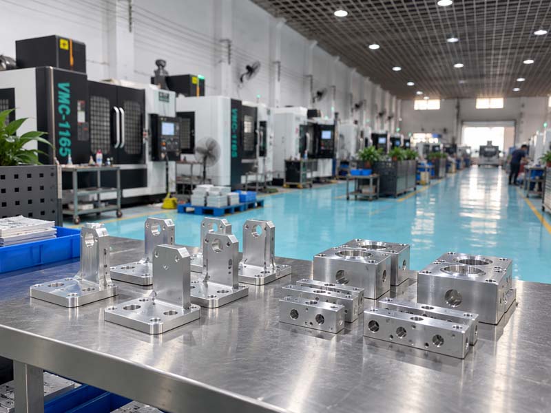
Milling brings rotating cutters to a supported workpiece. It suits pockets, slots, planar faces, mounting patterns and features accessible from selected directions. The machining plan still needs practical clamping surfaces and room for the cutter and holder. A feature visible on a CAD screen is not automatically reachable in a real setup.
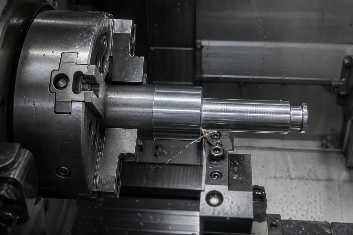
Let secondary features change the route
A turned flange may also need a bolt circle or wrench flats. A milled block may contain a precision bore. Those additional features do not necessarily change the best starting process; they create a sequencing and datum-transfer question. Discuss which surfaces will locate the part when it moves to another operation.
Send the complete model so the machining team can review which features belong in each setup. The available equipment, workholding and quantity determine whether a combined route is practical for the part.
| Planning factor | CNC milling | CNC turning |
|---|---|---|
| Primary motion | Rotating cutter works on a supported part | Workpiece rotates while the tool forms the feature |
| Natural geometry | Faces, pockets, slots and mounting patterns | Diameters, bores, shoulders and axial grooves |
| Access to review | Cutter direction, holder clearance and clamping | Axial/radial access and workpiece support |
| Secondary features | A bore may add another setup or operation | Flats or a bolt pattern may need secondary operations |
| Acceptance basis | Feature-specific tolerance and datum requirements | Feature-specific tolerance and datum requirements |
Compare complete routes
| Part geometry | Likely starting point | Review before committing |
|---|---|---|
| Stepped shaft or sleeve | Turning | Support, bore access, slenderness and secondary features |
| Pocketed mounting plate | Milling | Corner radii, tool reach and clamping |
| Ring with radial holes | Turning plus secondary operations | Angular location and datum transfer |
| Multi-face housing | Milling with a suitable setup strategy | Holder access and cross-face relationships |
A route with fewer operations is not always less expensive. Specialized workholding or difficult loading may offset the saved transfer. Conversely, a common setup can be valuable when it reduces the risk in a critical relationship. Request a process recommendation based on quantity, acceptance requirements and geometry together.
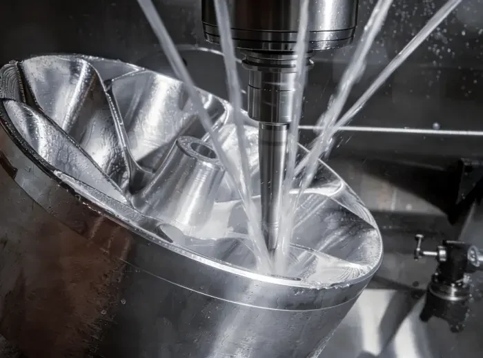
Tolerance belongs to the feature, not the process name
Neither milling nor turning guarantees a particular tolerance across an entire component. Tool condition, material, heat, clamping and measurement affect the outcome. A long flexible shaft needs different consideration from a short rigid ring even though both are turned.
Identify the surfaces that locate the part in service and the relationships that inspection must verify. Use quality and inspection planning to connect the drawing requirement to a suitable measurement method. Avoid ranking processes using a single accuracy number divorced from the feature being produced.
Milling vs Turning Decision Flow
- Dominant geometryIf the critical features are coaxial diameters, bores or shoulders, begin with turning.
- Functional faces and pocketsIf mounting faces, pockets, slots or hole patterns govern function, begin with milling.
- Both feature groups matterHold the primary datum in the base process, then plan the secondary operation around its transfer.
What This Means for Your Part
Send both the 3D model and a controlled drawing that identifies functional surfaces. Explain which features must share an axis, which planes locate the assembly and which holes need a controlled position. Add quantity and the required finish so that process and workholding choices reflect the actual order.
Compare the site's CNC turning and CNC milling information, then use drawing review to resolve the route. If multiple faces or angled features complicate access, the 5-axis strategy page provides additional context without assuming that every complex part needs simultaneous five-axis cutting.
- Identify the feature that establishes the part’s functional centerline or primary mounting face.
- Group coaxial diameters, threads and shoulders together on the drawing.
- Separate true prismatic features from details that can be completed in a secondary operation.