
CNC Machining Tolerances: What Engineers and Buyers Need to Know
Every machined part comes with dimensions that must be held within acceptable limits. Yet many engineering drawings carry tolerances that are unnecessarily tight, inconsistently applied, or missing entirely. For engineers designing parts and buyers procuring them, understanding what tolerances are realistic, how they affect cost, and how to communicate them clearly is essential. This guide explains the practical side of CNC machining tolerances from both manufacturing and procurement perspectives.
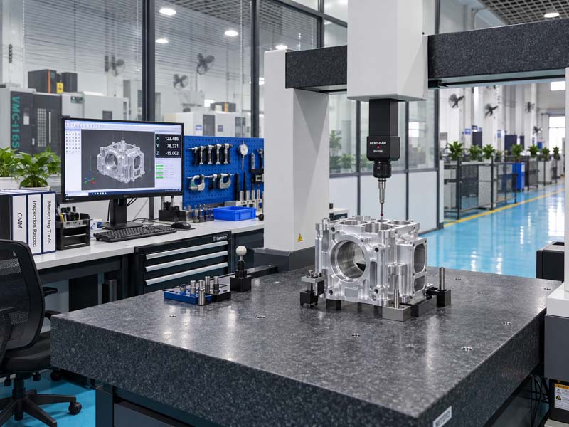
Coordinate measuring machine (CMM) inspection verifies that tolerances are met on critical features.
What Tolerances Can CNC Machining Achieve?
CNC machining is inherently a high-precision process, but the tolerance a part can achieve depends on material, geometry, machine condition, tooling, workholding, and the number of setups. As a general engineering reference, the following ranges are commonly achievable in typical CNC machining environments:
- Standard machining tolerance: ±0.005 in (±0.127 mm) – appropriate for most non-critical dimensions.
- Precision machining tolerance: ±0.002 in (±0.050 mm) – suitable for mating features, bearing bores, and general fits.
- High-precision tolerance: ±0.001 in (±0.025 mm) – requires careful control of tool deflection, thermal growth, and inspection setup.
- Ultra-precision tolerance: ±0.0005 in (±0.013 mm) or tighter – typically requires dedicated fixturing, temperature-controlled shop, and specialized equipment. Not every CNC shop can hold these values reliably.
It is important to note that these values are not guarantees from any specific supplier. Actual capability depends on part size, material, feature geometry, and the supplier's equipment and process control. A good practice is to discuss tolerance requirements with your machining partner early in the quoting phase.
How Tolerances Affect Machining Cost and Lead Time
Tighter tolerances increase cost in several ways:
Increased Machining Time
When a tolerance is tighter, the CNC program must use slower feed rates and multiple finishing passes. The operator may need to take lighter cuts to reduce tool deflection. This directly increases cycle time per part.
More Setups and Fixturing
To hold tight tolerances, the part may need to be machined in a single setup to avoid stack-up errors from re-clamping. This often requires custom fixtures or multi-axis machining, which adds programming and setup cost.
Tooling and Inspection
High-precision work requires sharper tools in good condition, more frequent tool changes, and rigorous inspection. CMM inspection, surface roughness measurement, and in-process gauging all add time and cost.
Higher Scrap Risk
The tighter the tolerance, the greater the chance of a part falling out of specification due to thermal expansion, tool wear, or material variability. Scrap and rework costs increase, sometimes significantly.
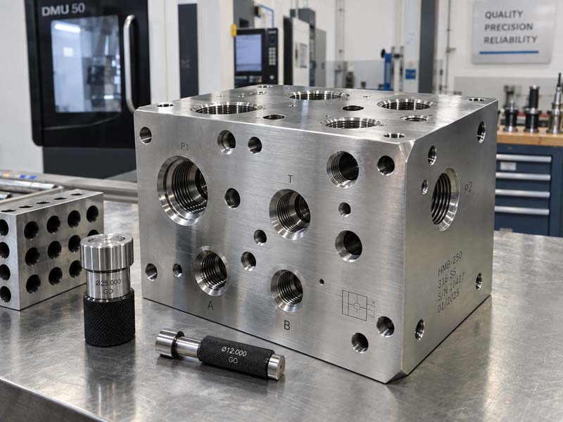
Inspecting critical hole tolerances on a manifold block with gauge pins.
For buyers, a drawing with many tight tolerances will receive higher quotes and longer lead times. Before adding a tight tolerance, ask: Is this dimension functionally critical? Could a looser tolerance still allow proper assembly and performance?
Common Tolerance Mistakes in Drawings
Through years of drawing review, our engineering team sees the same issues repeatedly. Avoiding these mistakes can save time and money.
Over-Tolerancing Every Dimension
Marking every dimension with ±0.1 mm or ±0.005 in is not helpful. Instead, use a general tolerance block (e.g., ISO 2768-m or ASME Y14.5) and only apply tighter tolerances where needed. This reduces ambiguity and unnecessary cost.
Missing Datum References
Tolerances without defined datums are ambiguous. For example, a position tolerance on a hole pattern requires a clear datum system (A, B, C) to define how the part is oriented during measurement. Without datums, inspection becomes guesswork.
Tolerances That Conflict With Geometry
Specifying a flatness tolerance of 0.01 mm on a thin-walled part that will distort during machining is unrealistic. The engineer must consider material behavior and part stiffness.
Ignoring Tool Access and Radii
An internal corner with a 0.1 mm radius is difficult to produce with a standard end mill. The smallest corner radius typically equals the cutter radius. Sharp internal corners (0 radius) require electrical discharge machining (EDM) or additional operation. Drawing callouts should reflect achievable tool geometries.
How to Specify Tolerances Correctly for CNC Parts
To avoid confusion and extra cost, follow these practical guidelines:
- Use a general tolerance note (e.g., ±0.2 mm for all untoleranced linear dimensions).
- Apply tighter tolerances only on features that mate with other parts or affect function (e.g., bearing bores, shaft fits, bolt hole patterns).
- Define a clear datum structure. For simple prismatic parts, use three mutually perpendicular surfaces (A, B, C).
- Consider surface finish as part of tolerance. A surface roughness of Ra 1.6 μm or better is usually needed for tight fits.
- Specify thread tolerances using standard classes (e.g., 6H for internal threads, 6g for external).
- Provide a 2D drawing alongside the 3D model. Many shops rely on the 2D drawing for tolerance information since 3D models often lack GD&T annotations.
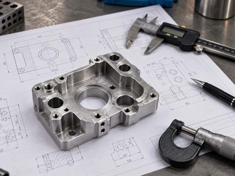
Inspecting a CNC machined housing against the drawing using standard gauges.
How Suppliers Evaluate Tolerance Requirements
When a CNC machining supplier receives a drawing, they immediately assess whether the tolerances are machinable, how much the part will cost, and what risks exist. Experienced suppliers consider:
- Machine capability: Can our CNC mills and lathes hold these values consistently? Do we have the right tools and probes?
- Material machinability: Aluminum and brass are easier to hold tight tolerances than stainless steel or titanium, which cause more thermal expansion and tool wear.
- Number of setups: Can all critical dimensions be achieved in one setup? If not, tolerance stack must be evaluated.
- Inspection plan: How will we verify each critical dimension? Do we need CMM, optical comparator, or manual gauges?
- Secondary operations: If the part requires heat treatment or surface finishing, does that affect dimensions? Post-plating tolerances must be accounted for in the drawing.
As a buyer, you can help the supplier by ensuring your drawing is complete, unambiguous, and includes all critical dimensions with tolerances. A well-prepared drawing leads to accurate quotes and reduces the likelihood of costly engineering change orders later.
Practical Takeaways
Tolerances are not just numbers on a drawing — they directly influence cost, lead time, and part quality. By applying tolerances only where functionally necessary, defining clear datums, and working with a CNC machining partner early in the design phase, you can achieve the precision your part requires without overspending.
If you are preparing a new project, consider sending your drawing to a precision CNC machining facility for a manufacturability review. An experienced engineering team can often suggest small changes that reduce cost without compromising performance.