
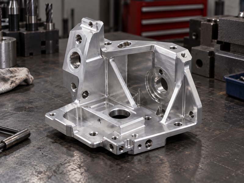
Why Design for CNC Machining Matters More Than You Think
A part that looks simple on a CAD screen can be difficult, slow, or expensive to machine. Small design decisions—like a sharp internal corner, an unnecessarily tight tolerance, or a thin wall—can increase setup time, require special tooling, and raise scrap rates. Understanding how CNC milling and turning actually work helps engineers create designs that are faster to produce and more cost-effective.
This guide covers the key design rules that affect machinability. Whether you are sending a drawing for a prototype or a production run, these guidelines will help you avoid common mistakes and get better quotes.
Wall Thickness: Balancing Strength and Machinability
Thin walls are a common source of problems in CNC machining. When a wall is too thin, the material cannot resist cutting forces without vibrating or deflecting. This leads to chatter, poor surface finish, and dimensional inaccuracy. For metal parts, a minimum wall thickness of 0.040 inch (1 mm) is a general guideline, but the actual safe minimum depends on the material, the part size, and the depth of the wall.
Aluminum allows slightly thinner walls than stainless steel because it is easier to cut. Plastics like nylon or acetal can be machined with walls as thin as 0.030 inch, but they are more prone to melting and burr formation. Deep thin walls are especially risky: a wall that is 0.060 inch thick and 2 inches tall will deflect significantly under side cutting forces. If a thin wall is unavoidable, consider leaving extra stock for a finish pass, using a smaller depth of cut, or adding temporary supports that can be removed after machining.
How Thick Is Thick Enough?
A rule of thumb: keep wall thickness at least 1/40 of the wall height. For example, a 2-inch-tall wall should be at least 0.050 inch thick. However, this is a starting point, not a guarantee. The actual requirement depends on the material's modulus of elasticity, the tool diameter, and the rigidity of the setup. When in doubt, thicken the wall slightly—it adds little material cost but saves machining headaches.
Internal Corner Radii: The Most Overlooked Cost Driver
Sharp internal corners are a problem in CNC milling because the cutting tool is round. A 90-degree internal corner cannot be cut cleanly with a square end mill—the tool leaves a radius equal to its own radius. To achieve a sharp corner, you would need a tool with a diameter of zero, which is impossible. The result is either a visible corner radius or a secondary operation like EDM.
Designing internal corners with a radius of at least 1/3 of the pocket depth allows the use of a larger, stiffer tool. A 0.125-inch radius is a common minimum that works well with standard 1/4-inch end mills. If the corner must be very sharp, consider adding a small relief or specifying a separate finishing operation.
In CNC turning, internal corners on bores also matter. A sharp corner at the bottom of a blind hole requires a special tool or a separate process. Adding a small fillet simplifies the toolpath and reduces tool wear.
Deep Pockets and Cavities: Tool Reach and Deflection
Deep pockets are among the most challenging features in CNC milling. When the pocket depth exceeds 4–6 times the tool diameter, the extended tool length causes deflection. Deflection leads to tapered walls, poor surface finish, and potential tool breakage. For example, a 1/4-inch end mill sticking out 2 inches will deflect noticeably, especially in hard materials.
Design deep pockets with a gradual floor, avoid sharp internal corners, and consider leaving a corner radius that allows a larger tool. If possible, break a deep pocket into multiple shallower features or specify a different machining strategy like dynamic milling that uses a smaller axial depth of cut. For very deep cavities, electrical discharge machining (EDM) or 5-axis machining may be more practical.
Hole Design and Thread Considerations
Holes are a basic feature, but poor hole design can increase cost significantly. Standard twist drill sizes produce holes that are slightly oversized or undersized. If a precise hole diameter is required, specify a reaming operation and leave about 0.005–0.010 inch stock for the reamer. Blind holes should have a flat bottom or a standard drill point angle (118° or 135°); a sharp bottom corner is difficult to achieve.
Threads add complexity. Threaded holes require tapping, thread milling, or single-point threading. For holes smaller than about #4 (2.5 mm), tapping becomes fragile and thread milling is preferred. Choose standard thread sizes (UNC, UNF, metric coarse) whenever possible—special threads require custom tooling. The depth of a threaded hole should be at least 1.5 times the thread diameter for adequate engagement, but avoid full threads all the way to the bottom of a blind hole because the tap can break.
Tolerances: Not Every Dimension Needs ±0.001
A common mistake is over-tolerancing. Adding a tight tolerance to every dimension on the drawing drives up cost without improving function. CNC machining can typically hold ±0.005 inch (0.13 mm) as a standard commercial tolerance. Tighter tolerances, like ±0.001 inch (0.025 mm), require careful setup, temperature control, and sometimes multiple inspections. The cost of a part can double when tolerances are tightened from ±0.005 to ±0.001.
Identify which dimensions are critical for fit or function. Use GD&T to define datum references clearly, and allow looser tolerances on non-critical features. For example, a mounting hole position may be critical, but the outer contour may not. Communicate tolerance requirements in a way that the machinist can inspect easily.
Surface Finish: Matching Function to Cost
Surface roughness is another area where overspecification hurts cost. A general machined finish of 63–125 microinches Ra is acceptable for most parts. Finishes below 32 Ra require additional passes, slower feeds, and sometimes a separate finishing tool. Mirror finishes (below 8 Ra) are expensive and should be reserved for sealing surfaces or optical components.
If a smooth surface is needed only on one face, specify that face separately. Do not apply a low roughness value to all surfaces. Also note that surface finish interacts with tolerance: a tight tolerance on a rough surface is contradictory because the roughness bands overlap the tolerance zone.
Undercuts and Special Features
Undercuts require special tools or a different machining strategy. In milling, an undercut (a feature hidden behind a wall) often needs a lollipop cutter or a right-angle head. In turning, undercuts on the back side of a part may require a second setup or a live tool. Avoid undercuts if possible, or design them with a standard cutter radius and depth to keep them machinable with off-the-shelf tools.
Deep slots, long thin parts, and parts with multiple tapers also add complexity. Each unique axis of motion or tool change adds cycle time. The simplest geometry that meets the function is usually the most cost-effective.
Material Selection: Impact on Machinability
Material choice directly influences tool life, cutting speed, surface finish, and part deformation. Aluminum (6061, 7075) is the most machinable common metal, with good chip formation and low cutting forces. Stainless steel (304, 316) requires slower speeds, more rigid setups, and careful chip evacuation. Brass and copper machine nicely but produce stringy chips. Titanium and high-temp alloys need specialized tooling and are significantly more expensive to machine.
When specifying a material, consider the machinability rating. For example, free-machining steels like 12L14 are much easier to cut than 4140 hardened. If the part does not need high strength, choose a grade with good machinability to reduce machining time and tool cost.
Fixture and Workholding: Design with Setup in Mind
The way a part is held during machining affects dimensional accuracy and surface finish. A part with irregular contours or thin sections may be difficult to clamp without distortion. If possible, add flat clamping surfaces or machining allowance that can be removed later. Avoid designs that require complex custom fixtures, especially for low-volume parts.
Parts that are symmetrical about one axis are easier to fixture. Parts that require multiple setups (flipping, rotating) increase the risk of tolerance stackup. 5-axis machining can reduce setups, but should only be used when truly necessary to avoid higher programming and machine costs.
Putting It All Together: Practical DFM Checklist
Before sending a drawing for quote, review these points:
- Are all internal corners filleted with a radius suitable for a standard end mill?
- Is the wall thickness adequate to avoid vibration and deflection?
- Are deep pockets broken into shallower features or designed with a floor that allows a larger tool?
- Are hole sizes and thread types standard?
- Are tolerances applied only where functionally necessary?
- Is surface finish specified only on critical surfaces?
- Is the material choice optimized for machinability?
- Can the part be held securely without complex fixtures?
- Is the number of setups minimized?
By following these design guidelines, you will reduce machining time, lower scrap rates, and shorten lead times. A well-designed part is also easier for a supplier to quote accurately—saving you from unexpected cost overruns. Engineers who think like machinists produce parts that are not only functional but also economical to produce.