
A design engineer specifies a tolerance of ±0.01 mm on a bore diameter. The procurement team receives a high quotation. The machining supplier asks whether all dimensions truly require that level of precision. This situation repeats across countless projects every year. The question is not whether CNC machines can hold tight tolerances — they can. The real question is whether every tolerance specified on a drawing is necessary for the part to function correctly.
Understanding how tolerances affect machining cost, lead time, and manufacturability is essential for both engineers and buyers. Over-tolerancing a part — applying unnecessarily tight tolerances to features that do not require them — is one of the most common and costly mistakes in custom CNC machining. This guide explains how to choose realistic tolerances, what factors influence machining accuracy, and how to balance design requirements with production efficiency.
What Are CNC Machining Tolerances?
A tolerance is the permissible limit of variation in a physical dimension. In CNC machining, tolerances define how much a measured dimension can deviate from the nominal value specified on the drawing. For example, a shaft diameter of 20 mm with a tolerance of ±0.05 mm means the finished diameter must fall between 19.95 mm and 20.05 mm.
Tolerances are typically expressed in one of two ways:
- Bilateral tolerance: ±0.1 mm, ±0.05 mm, ±0.01 mm
- Unilateral tolerance: +0.05 mm / -0.00 mm
In addition to linear dimensions, geometric tolerances (GD&T) control form, orientation, and position features — such as flatness, parallelism, concentricity, and true position. These are equally important and often misunderstood.
It is important to understand that tighter tolerances increase machining difficulty, inspection time, and scrap risk. Choosing the right tolerance is not about making the number as small as possible — it is about making the number as large as possible while still allowing the part to function correctly.
Common Tolerance Ranges in CNC Machining
As a general engineering reference, CNC machining can typically achieve the following tolerance ranges under normal production conditions:
| Tolerance Grade | Typical Range | Application Examples |
|---|---|---|
| Standard | ±0.1 mm to ±0.2 mm | Non-critical features, clearance holes, general dimensions |
| Precision | ±0.05 mm | Bearing fits, locating features, general machined parts |
| High Precision | ±0.025 mm | Critical mating surfaces, precision shafts, guide pins |
| Ultra Precision | ±0.005 mm to ±0.01 mm | Hydraulic components, valve spools, high-precision tooling |
These values are for reference only. The achievable tolerance depends heavily on material, geometry, machine condition, cutting tools, workholding, and the skill of the machinist. A reliable CNC machining manufacturer will evaluate each feature individually and advise on realistic tolerance targets.
Factors That Affect CNC Machining Accuracy
Several factors determine whether a tight tolerance can be consistently achieved in production. Understanding these factors helps engineers and buyers set realistic expectations.
Machine Capability
The machine itself sets a baseline for achievable accuracy. A well-maintained 3-axis machining center can typically hold ±0.05 mm for most features. A high-performance 5-axis machine with thermal compensation may hold tighter tolerances over large parts. However, machine specification sheets often quote accuracy under ideal laboratory conditions — real-world production environments introduce variables that reduce repeatability.
Material Machinability
Materials behave differently during cutting. Aluminum 6061 is stable and easy to machine, making it suitable for tighter tolerances. Stainless steel, especially grades like 316, work-hardens and generates more heat, making dimensional control more challenging. Titanium and hardened tool steels require rigid setups and careful tool path strategies to avoid deflection and heat-induced expansion.
Part Geometry
Thin walls, deep pockets, long slender features, and unsupported sections are prone to deflection under cutting forces. Maintaining tight tolerances on these features is inherently difficult. For example, a thin-walled aluminum housing with a wall thickness of 1.5 mm may require multiple finishing passes and specialized workholding to hold ±0.05 mm on critical bores.
Tool Deflection and Wear
Long tools deflect more than short tools. A deep pocket machined with a tool that has a 5:1 length-to-diameter ratio will have more variation than a shallow feature cut with a stubby end mill. Tool wear also affects dimensions over the life of the tool. Modern CNC controls can compensate for some of these effects, but physical limits remain.
Thermal Effects
Cutting generates heat. Both the workpiece and the machine structure expand with temperature changes. A part measured at 8:00 AM in a cold workshop may measure differently at 2:00 PM after the machine has warmed up and the ambient temperature has risen. Controlling thermal conditions is essential for holding tolerances below ±0.01 mm.
Tolerance and CNC Machining Cost
This is one of the most important concepts for both design engineers and procurement professionals to understand: tighter tolerances increase cost. The relationship is not linear. Moving from ±0.1 mm to ±0.05 mm may add 10–15% to machining time and inspection effort. Moving from ±0.05 mm to ±0.01 mm can easily double or triple the cost of the affected operation.
Why does tighter tolerance increase cost?
- More machining time: Finishing passes must be slower and lighter to reduce tool deflection and heat generation.
- Additional setups: Some tight-tolerance features require multiple setups or dedicated fixtures to control datum references.
- Special tooling: Reamers, boring bars, and custom ground tools may be required instead of standard end mills.
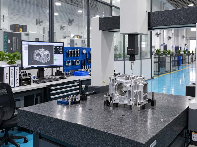
- In-process inspection: Machinists must stop production to measure critical dimensions, often using CMM, height gauges, or micrometers.
- Higher scrap risk: When a dimension falls outside the tolerance band, the part may be scrapped. Higher precision increases the probability of rejection.
- Slower production rates: Tighter tolerances reduce feed rates and depth of cut, directly increasing cycle time.
For a precision CNC machining project, the most cost-effective approach is to specify tight tolerances only where they are functionally necessary. All other dimensions should use standard tolerances. This approach is often called "tolerance grading" or "selective tolerancing."
How to Specify Tolerances on a Drawing
A well-prepared drawing communicates clearly to the machining team. Here are practical guidelines for specifying tolerances effectively.
Use a General Tolerance Block
Most engineering drawings include a general tolerance note. For example:
- "Unless otherwise specified, all dimensions ±0.2 mm"
- "General tolerance ISO 2768-m"
- "All untoleranced dimensions ±0.1 mm"
This avoids cluttering the drawing with individual tolerance callouts for every dimension. Only critical features should receive dedicated tolerance values.
Identify Functional Dimensions
Ask: Which dimensions affect assembly, performance, or safety? These are the dimensions that need tighter control. Typical functional dimensions include:
- Bearing journal diameters
- Shaft-to-bore clearance fits
- Locating pin positions
- Concentricity between rotating features
- Sealing surface flatness
All other dimensions can remain at the general tolerance level.
Use GD&T Where Appropriate
Geometric tolerancing controls form and position more precisely than linear tolerances alone. For example, specifying a position tolerance of Ø0.1 mm for a bolt hole pattern ensures the parts will assemble correctly, even if the hole diameters themselves have a wider tolerance. GD&T is especially valuable for complex parts with multiple critical interfaces.
Avoid Over-Tolerancing
Over-tolerancing is the practice of applying unnecessarily tight tolerances to non-critical features. This often happens when a designer uses a single tolerance value across the entire drawing for consistency, or when a designer lacks manufacturing experience. Over-toleranced parts cost more to produce without gaining any functional benefit.
During a CNC machining drawing review, experienced engineers identify over-toleranced features and suggest adjustments. This is a normal part of the quotation and production preparation process.
Tolerance Considerations for Different Materials
The material selected for a part directly influences the achievable tolerance and the cost of achieving it.
| Material | Machinability | Typical Tolerance (Reference) | Key Considerations |
|---|---|---|---|
| Aluminum (6061, 7075) | Excellent | ±0.025 mm on simple features | Stable, low cutting forces, good surface finish |
| Mild Steel (1018, 1215) | Good | ±0.05 mm | Predictable cutting, reasonable tool life |
| Stainless Steel (304, 316) | Moderate | ±0.05 mm to ±0.1 mm | Work-hardening, heat buildup, tool wear |
| Brass (360) | Excellent | ±0.025 mm | Low cutting forces, good dimensional stability |
| Titanium (Grade 5) | Difficult | ±0.05 mm on rigid sections | High cutting temps, tool deflection, vibration |
| Engineering Plastics (Delrin, Nylon) | Good to Moderate | ±0.05 mm to ±0.1 mm | Thermal expansion, moisture absorption, clamping distortion |
It is important to note that these are general engineering references, not guarantees. The actual tolerance achievable for a specific part depends on geometry, fixture design, tool selection, and machine condition.
Tolerance and Process Selection
The machining process itself affects achievable tolerances. Understanding which process is best suited for which tolerance helps engineers design parts that are easier to manufacture.
CNC Milling
3-axis milling is the most common process for prismatic parts. Standard milling can hold ±0.1 mm on general dimensions. Precision milling with careful tool selection and finishing passes can achieve ±0.025 mm on small features. 5-axis milling reduces the need for multiple setups, which often improves positional accuracy between features on different faces of the part.
CNC Turning
Turning produces cylindrical features with good concentricity and roundness. A precision CNC lathe can hold ±0.01 mm on diameters under stable conditions. However, long slender shafts and thin-walled tubes require special attention to deflection and clamping distortion.
Grinding
For tolerances below ±0.005 mm, grinding is often required after initial machining. This is a separate process that adds setup time and cost. Most machined parts do not require grinding unless extremely tight fits or surface finishes are specified.
Which Process Should You Choose?
The answer depends on the part geometry, material, quantity, and tolerance requirements. A simple bracket with ±0.1 mm tolerances can be efficiently produced on a 3-axis mill. A complex aerospace component with multiple critical tolerances on different faces may require 5-axis machining with in-process inspection. A high-volume shaft with tight diameter control may be more economical to turn on a Swiss-type lathe.
Discussing process options with an experienced CNC machining supplier during the quotation stage helps align expectations and avoid costly surprises later.
Practical Tips for Buyers and Engineers
Drawing on real-world procurement and engineering experience, here are actionable recommendations for anyone involved in specifying or sourcing CNC machined parts.
For Design Engineers
- Start with standard tolerances. Only tighten dimensions that are functionally critical.
- Use a general tolerance block to avoid cluttering the drawing.
- Consider how the part will be held during machining. Features that require tight tolerances should ideally be machined in the same setup.
- Design datum features that are accessible and repeatable. Avoid using thin walls or non-machined surfaces as primary datums.
- Specify surface roughness requirements only where necessary. Combining tight tolerance with a fine surface finish adds significant cost.
For Procurement Professionals
- Review the drawing for over-toleranced features before sending it for quotation. If you are unsure, ask an engineer or the supplier for feedback.
- Provide a complete set of requirements: 3D model (STEP or IGES), 2D drawing with tolerances, material grade, quantity, and any surface finishing requirements.
- Ask the supplier which tolerances are most challenging to achieve. Their response reveals a lot about their engineering depth.
- Be realistic about lead time. Parts with tight tolerances require slower machining speeds, more inspection, and potentially multiple setups.
- Compare quotations carefully. A significantly lower price may indicate that the supplier has not fully understood the tolerance requirements.
Common Tolerance Problems and How to Avoid Them
Even experienced engineers encounter tolerance-related problems during production. Here are common issues and how to prevent them.
Problem: Tolerance Stack-Up in Assemblies
When multiple parts are assembled, individual tolerances accumulate. A clearance fit that appears adequate on paper may become too tight or too loose when all parts are at their tolerance limits. The solution is to perform a tolerance stack analysis during the design phase and adjust critical fits accordingly.
Problem: Measuring Discrepancies
The machinist measures a bore at 20.02 mm with an internal micrometer. The inspector measures the same bore at 20.01 mm with a CMM. Who is correct? Measurement tools have their own accuracy limits, and temperature, operator technique, and calibration status all affect results. Agreeing on the measurement method and environment is essential for tight-tolerance features.
Problem: Datum Ambiguity
If a drawing shows a geometric tolerance without clearly defining the datum reference, the machinist and inspector may interpret it differently. This leads to rejected parts and wasted time. Always define datums clearly and ensure they are physically accessible on the part.
Problem: Deformation After Machining
A thin-walled part measures within tolerance on the machine, but after unclamping, the wall distorts and the dimension shifts. Stress relief, clamping strategy, and leaving stock for a final finishing pass after roughing are common solutions.
How a CNC Machining Partner Can Help
Choosing the right tolerances is a collaborative effort between the design team and the machining supplier. A knowledgeable manufacturer provides valuable input during the drawing review stage. They can identify features that will be difficult to hold, suggest alternative tolerancing schemes, and recommend design changes that improve manufacturability without compromising function.
This engineering review is one of the most valuable services a machining partner offers. It reduces quotation uncertainty, minimizes production risks, and often leads to cost savings for the customer. When you receive a quotation that includes comments about specific tolerances or suggestions for alternative approaches, that is a sign of a supplier who understands machining at a practical level.
The goal is not to eliminate tight tolerances. The goal is to apply them precisely where they are needed — and avoid applying them where they are not.