Introduction
CNC machining is one of the most versatile and widely used manufacturing processes for producing high-precision metal and plastic parts. From prototypes to production runs, understanding the principles of design for CNC machining (DFM) is crucial for engineers and product designers to ensure parts are manufacturable, cost-effective, and meet performance requirements. This guide provides practical insights into material selection, geometric design rules, tolerance considerations, surface finishes, and quality inspection that can help you make informed decisions during the design phase.
Whether you are developing a new product or optimizing an existing design, applying DFM principles early can reduce machining time, minimize scrap, and avoid costly redesigns. Let's dive into the key aspects that every designer should know.
1. Material Selection for CNC Machining
Choosing the right material is the first step in a successful CNC machining project. The material affects machinability, part strength, weight, corrosion resistance, and cost. Common materials include aluminum alloys, stainless steel, brass, engineering plastics (e.g., Delrin, Nylon), and specialty alloys.
Aluminum Alloys
Aluminum is the most popular material for CNC machining due to its excellent machinability, light weight, good strength-to-weight ratio, and natural corrosion resistance. Alloys like 6061-T6 and 7075-T6 are widely used for brackets, housings, enclosures, and structural components. Aluminum is also easy to anodize, providing enhanced wear resistance and aesthetic options.
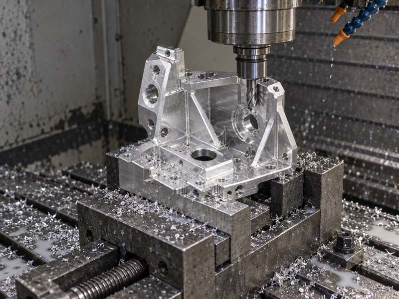
A typical aluminum bearing bracket being machined on a CNC mill.
Stainless Steel
Stainless steel grades like 304 and 316 offer high strength, excellent corrosion resistance, and are suitable for medical, food, and marine applications. However, they are harder to machine than aluminum, requiring slower speeds, rigid setups, and specialized tool coatings. Designers should avoid thin walls and deep cavities to reduce tool deflection and heat buildup.
Brass
Brass is prized for its excellent machinability, good electrical conductivity, and attractive appearance. It is commonly used for fittings, valves, and decorative components. Brass achieves fine surface finishes and tight tolerances easily, making it ideal for threaded parts and small precision components.
Engineering Plastics
Plastics like Delrin (POM), Nylon, and PTFE are lightweight, self-lubricating, and resistant to chemicals. They are often used for bushings, bearings, insulators, and food-contact parts. When designing plastic parts for CNC, consider thermal expansion and avoid sharp internal corners to prevent stress cracking.
2. Key Design Rules for Machinability
To ensure your part can be machined efficiently and economically, follow these design guidelines:
Avoid Sharp Internal Corners
Sharp inside corners cannot be achieved with standard round cutting tools. Always specify an internal corner radius at least equal to the radius of the intended tool (commonly 1/8", 1/4", or 1/16"). Larger radii allow larger tools, faster material removal, and better surface finish. If a sharp corner is absolutely necessary, consider using a smaller end mill or a secondary EDM operation, which increases cost.
Maintain Uniform Wall Thickness
Variations in wall thickness can cause chatter, vibration, and dimensional inaccuracies. For metal parts, avoid thin walls (<0.020" for aluminum, <0.040" for steel) unless supported by fixturing. Uniform thickness promotes consistent machining forces and reduces risk of distortion.
Design for Standard Tool Lengths
Deep cavities and tall features require long tools, which are less rigid and more prone to deflection. Keep feature depths less than 3-4 times the tool diameter whenever possible. For deeper features, plan for progressive tooling or consider using a different process like EDM or gun drilling.
Include Adequate Draft Angles
Although not always required in CNC machining (unlike injection molding), draft angles help in releasing the part from workholding fixtures and improve chip evacuation. For vertical walls, a small draft of 0.5° to 1° is recommended if the part will be machined in multiple setups.
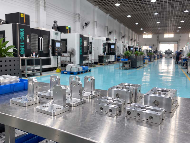
High-quality machined aluminum parts showcasing consistent features and finishes.
3. Tolerances and Surface Finishes
Understanding achievable tolerances and surface finishes is essential for communicating requirements to the machine shop and controlling costs.
Standard Tolerances
For CNC machining, standard linear tolerances are typically ±0.005" (0.13 mm). Tighter tolerances down to ±0.001" (0.025 mm) are possible but require slower feeds, multiple setups, and more inspection time, increasing cost. When specifying tolerances, only apply tight tolerances where functionally necessary (e.g., bearing seats, mating surfaces). Leave generous tolerances everywhere else.
Geometric Tolerances (GD&T)
For complex parts, use GD&T symbols like flatness, parallelism, concentricity, and true position to control form and location. Be sure to reference datums correctly and avoid over-constraint. Coordinate measuring machines (CMMs) and vision systems are used to verify these features.
Surface Finishes
CNC machining produces as-machined surfaces with micro-ridges from tool marks. Typical surface roughness (Ra) ranges from 3.2 μm (standard) to 0.8 μm (fine). For smoother finishes, specify operations like polishing, bead blasting, or grinding. Common post-processing options include anodizing (for aluminum), passivation (stainless steel), plating, or powder coating. Anodized aluminum is widely used for enclosures and brackets due to its combination of durability and appearance.
4. Common Design Pitfalls and How to Avoid Them
- Over-tightening tolerances: Avoid specifying ±0.001" on every dimension. This slows down machining and increases inspection time unnecessarily.
- Ignoring tool access: Design features that cannot be reached by a standard tool (e.g., deep slots with non-standard widths) often require custom tools or EDM, driving up cost and lead time.
- Unbalanced thin sections: Long thin walls or large unsupported areas may vibrate during machining, causing chatter and poor finish. Add ribs or bosses to stiffen the part.
- Too many setups: If a part must be flipped multiple times, each setup introduces positional errors. Try to machine all features from one side or use two setups max.
- Sharp edges: Sharp edges are prone to burrs and can be dangerous. Specify edge breaks (chamfer or radius) of 0.005"-0.020" to improve safety and aesthetics.
5. Inspection and Quality Control
Quality assurance is integral to CNC machining. After machining, parts are inspected to verify dimensions, surface finish, and integrity. Common inspection methods include:
- First Article Inspection (FAI): Comprehensive check of the first part produced to ensure all features meet the drawing.
- CMM Inspection: Using a coordinate measuring machine for precise measurement of complex geometries, especially with GD&T.
- Go/No-Go Gages: For threads, holes, and press-fit features.
- Surface Roughness Measurement: Using profilometers to verify Ra values.
- Vision Systems: For quick measurement of multiple features on smaller parts.
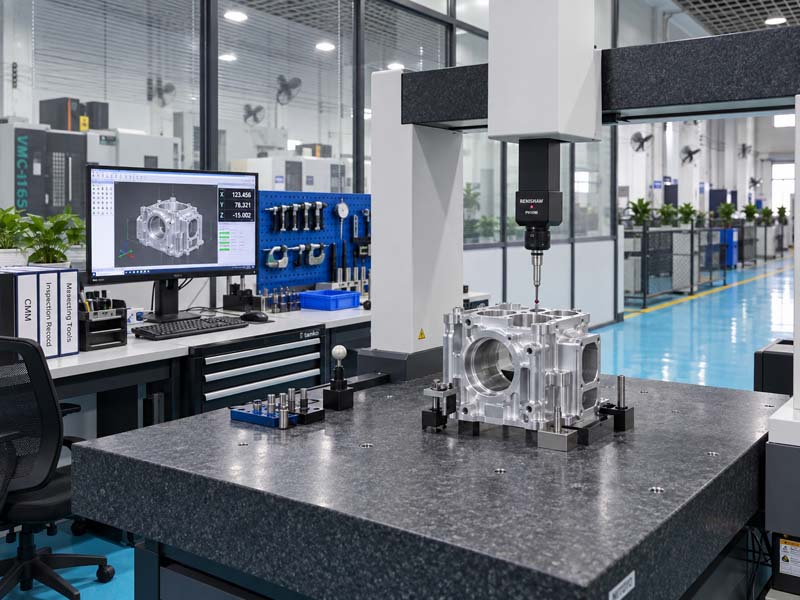
Precision CMM inspection ensures that critical dimensions and geometric tolerances are met.
6. Cost Reduction Strategies
To reduce CNC machining costs, consider the following:
- Reduce complexity: simpler geometries machine faster.
- Minimize material removal: design near-net shape or use stock sizes close to final part dimensions.
- Specify standard tolerances and surface finishes unless strictly required.
- Batch multiple parts on one fixture plate to reduce setup time.
- Choose materials with high machinability (e.g., aluminum 6061 over 7075 if strength permits).
- Design parts that can be machined in a single or two setups.
Conclusion
Designing for CNC machining is a collaborative effort between engineers and machinists. By understanding the capabilities and limitations of the process, you can create parts that are functional, manufacturable, and cost-effective. Whether you are working with aluminum, steel, brass, or plastics, following the guidelines discussed will help you achieve better results. Always communicate clearly with your CNC machining partner—share your design intent, tolerance rationale, and critical features to ensure a smooth transition from design to production.
For more detailed guidance on specific materials, tolerances, or surface finishes, explore the other technical guides on our website. We are committed to helping you bring your designs to life with precision and quality.