
Quick Answer
A gauge R&R study splits measurement variation into two parts: repeatability, the spread one operator gets when measuring the same feature twice, and reproducibility, the shift that appears when other operators repeat the exercise. On machined parts it matters because a gauge that consumes a large share of the tolerance leaves the shop chasing variation it cannot see. Run it on the features that govern fit, not on the dimension easiest to reach.
Key Takeaways
- Repeatability belongs to the gauge, fixture and method; reproducibility belongs to the people using them.
- Study parts must span the real production spread, or the result flatters the gauge.
- The share of tolerance consumed matters more than the raw variation figure.
- Clamping, temperature and burrs usually surface as repeatability problems.
- A failed study points at the gauge, the fixture or the drawing, and those cost very differently.
What Gauge R&R Measures, and What It Leaves Out
Gauge R&R, often written gage R&R, is the part of a measurement systems analysis that deals with precision rather than accuracy. Repeatability is the variation one operator gets when measuring the same feature several times. Reproducibility is the variation that appears when other operators repeat the measurement with the same gauge.
Equipment can be accurate and still fail the study. Calibration and bias checks cover accuracy; the R&R run asks a narrower question, whether the method can tell two parts apart. A gauge with fine resolution in a loose fixture reads the fixture, not the part.
Linearity and stability sit outside the run: one asks whether error stays consistent across the range, the other whether the gauge drifts over weeks. A single figure for measurement capability usually blends all three.
Setting Up a Study That Means Something
The parts come first. A study needs a set that covers the spread the process actually produces, because the calculation compares measurement variation with part-to-part variation. Pull ten parts across several days rather than ten pieces from one bar and one setup; parts sitting within a few microns of each other make the gauge look worse than it is.
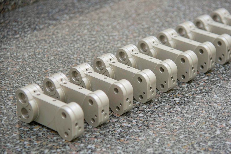
Typical practice is three operators and three trials each, order randomized and part identity hidden. A number the operator can read turns the second trial into a memory exercise. The gauge should be calibrated and used the way production uses it, with the same stand, anvils and clamping force.
Resolution deserves a check before the run. An instrument reading in 0.01 mm against a ±0.02 mm callout has used a quarter of the band before the part is touched, and the micrometer vs caliper comparison covers how the two instruments differ here.
Reading %GRR Against the Tolerance
The headline number is %GRR, measurement variation as a percentage of the tolerance width. That denominator is a choice, and it is where arguments start: the same gauge looks capable against a ±0.1 mm callout and unusable against ±0.01 mm.
Common industry practice sorts results into three bands. Below roughly 10 percent the method is generally accepted, 10 to 30 percent is accepted with conditions attached, and above 30 percent needs attention before the data is used for acceptance. Treat the bands as convention rather than law; on a bore that sets bearing fit, a stricter internal limit is reasonable.
A second figure is the number of distinct categories the method can resolve. Five or more is a common screen; below that the gauge is close to a go/no-go decision maker. Attribute gauges are a separate case, judged by an attribute agreement study, and the go no-go gauge guide explains what they can confirm.
Why Studies Fail on Machined Parts
Most failures are not the gauge: the parts were too similar. Ten pieces from one bar in one setup may vary less than the measurement error, so the ratio looks poor although the gauge is adequate for production spread.
Clamping distortion comes second. Thin walls, frame parts and bores near an edge move when a vise closes, so a part checked in the fixture and a part checked on the plate disagree.
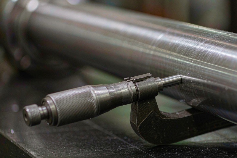
Edge condition comes third. A chamfer on one part and not the next changes how the anvil seats. Technique follows: ratchet versus friction thimble, seating force, and whether the operator rocks the micrometer to find the high point. Routine checks rarely catch this, which is why in-process inspection and a method study answer different questions.
Common Mistakes and What to Do Next
Five mistakes account for most unusable studies: a master part instead of production parts, parts near the limit quietly left out, operators who are not blinded, a method changed halfway, and one %GRR quoted across features measured with different setups.
The result points to different fixes. Poor repeatability with good reproducibility means the gauge, fixture or seating method is at fault, and a fixture change is often cheaper than a new instrument. The reverse pattern points at training, clamping force or reading technique.
Record the study beside the inspection plan so the next reviewer can see which gauge, fixture and tolerance the number refers to. That context usually travels with the first article package, and the first article inspection checklist covers what else belongs in it.
FAQ
Is gauge R&R the same as a calibration check?
No. Calibration confirms the instrument reads correctly against a known reference. The R&R run asks whether the whole method, operator included, can separate one part from another.
How many parts and operators does a study need?
Ten parts, three operators and three trials is a common starting point, enough to expose operator effects without consuming a week of inspection time.
Should the denominator be the tolerance or the process spread?
Use the tolerance to decide whether the method can release parts to the drawing, and the process spread to decide whether it can support a control chart. When the two answers differ, that gap is the finding.