Quick Answer
Surface texture direction is the lay — the dominant pattern of tool marks on a machined face. It is specified as a direction symbol next to the finish value, and it matters most on sealing and sliding faces, where a lay running across the leak path can defeat an otherwise good Ra number. Ra describes average height deviation and says nothing about direction, so two faces with the same Ra can seal very differently.
Key Takeaways
- Ra is an amplitude average; it carries no information about the direction of the tool marks.
- Lay direction uses standard symbols placed around the surface texture symbol.
- Continuous circular lays suit rotating seals; cross-hatched lays suit static gasket faces.
- Rz predicts sealing better than Ra on faces with isolated deep marks.
- Adding a lay requirement is nearly free at the machine but costly after the part has run.
Why Ra Alone Is Not Enough
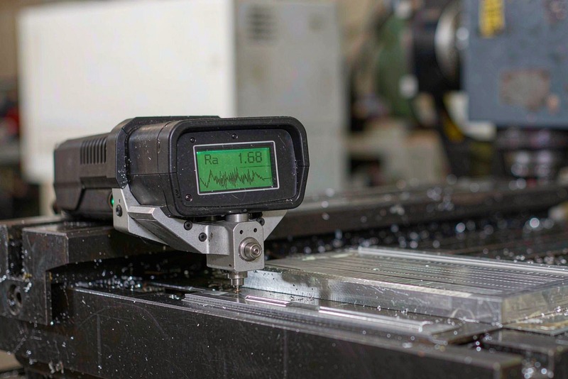
Ra reduces a surface to one number: the arithmetic mean of the profile deviation from its center line. It is fast to measure and repeatable, but the weakness is structural — an averaging filter flattens exactly the features that decide whether a joint leaks.
Two faces finished to the same Ra of 1.6 µm behave differently. One was face milled with a fine feed, leaving shallow parallel grooves. The other was finished with a wider feed and then partly polished, leaving most of the surface smooth but a few deep marks in it. Under compression, a gasket bridges the shallow field but cannot fill the deep valleys, giving the seal path a leak channel. Ra reports both as equivalent; Rz, the average peak-to-valley height within the sampling length, separates them.
That is why a tight Ra on a sealing callout frequently also needs an Rz limit or an explicit lay direction.
Reading Lay Direction Symbols
The direction position on a surface texture symbol uses a small set of conventional marks. A line parallel to the plane of projection means the lay runs along it; a perpendicular line means it crosses; X means it crosses in two directions; M means multidirectional, as from lapping; C means approximately circular about a center; and P means particulate, typical of shot-blasted faces.
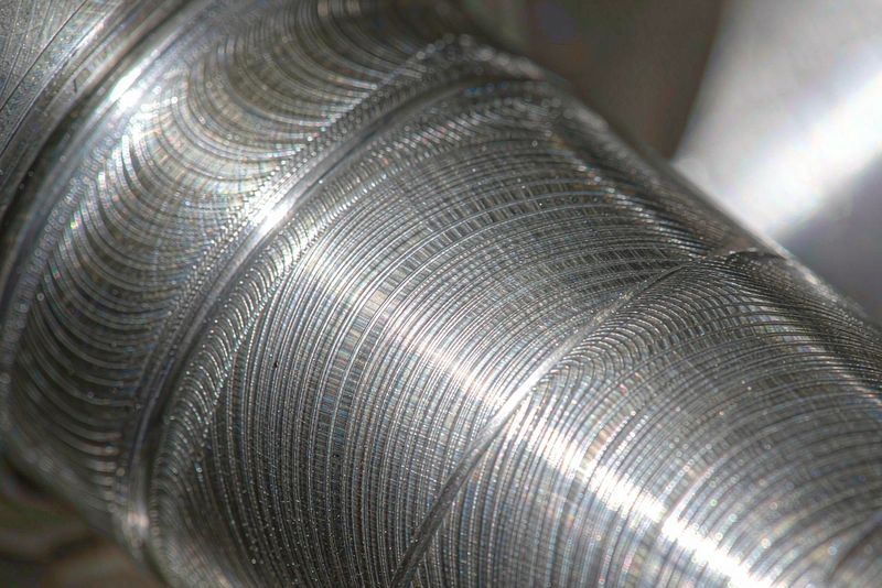
The practical question is which pattern the interface wants. A rotary shaft seal on a turned journal wants a fine circular lay with no axial score, because an axial scratch gives the lip a path to pump oil along. A static cover sealed by a flat gasket does better with a cross-hatched face, so the leak path breaks into short segments instead of one channel. An anodized front panel usually wants a uniform directional lay, because anodizing amplifies whatever pattern the cutter left.
How the Machining Process Sets the Lay
The lay is not applied after the fact. It follows from the tool path and cutter geometry, so it is set at process planning and is hard to change cheaply later.
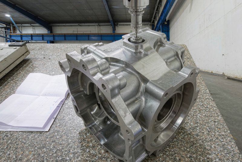
Face milling leaves a pattern set by cutter diameter, stepover and insert geometry. A single-pass face mill sweeps visible arcs, while overlapping passes produce a scalloped pattern. Scallop depth scales with stepover and cutter tilt, so a face mill slightly out of tram leaves the pattern deeper on one side.
Peripheral end milling of a pocket floor leaves marks parallel to the tool path, with a cross-hatch where passes overlap. Turning produces a helical lay with a pitch equal to the feed per revolution, and on a seal journal that pitch matters: too coarse a feed leaves a thread-like path that can pump fluid. Grinding and lapping produce the finest, most direction-controlled lays, with superfinishing removing the direction almost entirely.
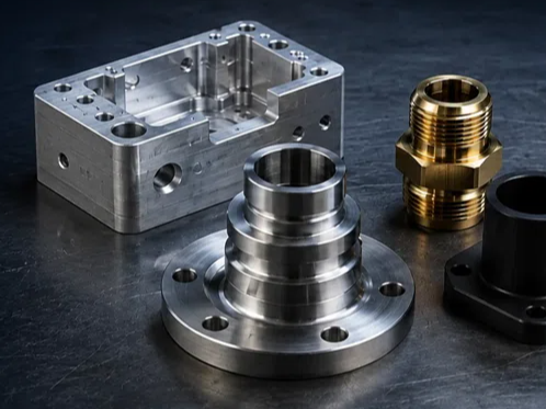
Reviewing the CNC machining surface finish options before releasing a drawing beats negotiating a change after the first article arrives.
Specifying Texture on a Drawing
A callout that survives the trip from design to inspection usually has four parts: the parameter, the value, the cutoff, and the direction. Omitting the cutoff is the most common gap, because Ra and Rz both change with the sampling length used to compute them. A supplier measuring with a different cutoff can return a number that looks compliant while describing a different surface.
Specify direction where the interface is functional, and leave it off where it is not. A face that takes a gasket or a seal lip needs a direction note; a clearance face inside a housing usually does not, and adding one buys nothing while inviting a measurement argument. Use an area-limited note when only part of a face is functional: marking a whole face to sealing grade when a narrow band around a port seals raises cost for no gain. The guide to preparing a 2D drawing for machining covers where these local notes belong.
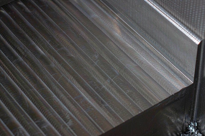
Measuring and Verifying Texture Direction
The lay is visual and cannot be measured with a stylus profilometer, which reports amplitude along one trace. Verification therefore uses two tools answering different questions.
Visual comparison is the first. A comparator chart with standard specimens lets an inspector judge the approximate grade and confirm direction under controlled lighting, which is fast and adequate for a circular lay on a seal journal.
Stylus or optical profiling is the second. A traverse across the lay and one along it give different Ra values on the same face, and that gap is diagnostic: a wide difference confirms a strong lay. On a sealing face, the profile across the leak path predicts performance, so the trace direction belongs in the inspection plan. The datum selection guidance applies to texture inspection as it does to dimensional work.
Common Mistakes
Treating Ra as a complete specification. Ra is one parameter on one trace; it says nothing about direction, depth or waviness. Where a joint must seal, pair it with Rz or a note.
Mirroring a direction note from a similar part. A lay that works on a shaft journal is often wrong on a gasket face, so the note should follow the interface, not the part family.
Asking for the finest finish everywhere. Cost rises steeply at the fine end, and a polished face can be worse than a controlled one for a gasket because it gives the elastomer fewer places to grip.