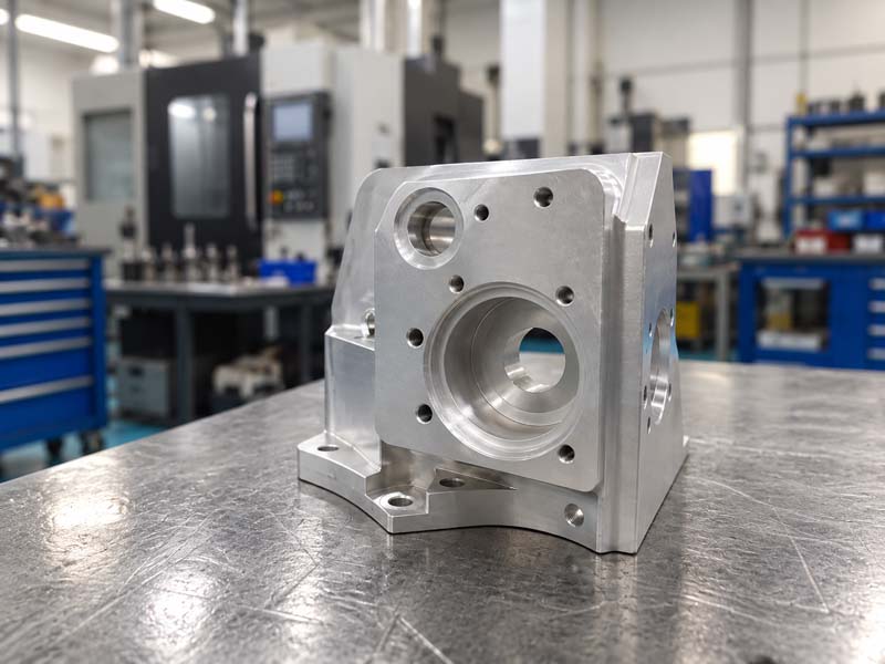
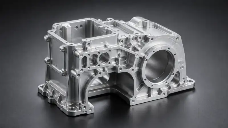
In the world of CNC machining, tolerances are the language of precision. They define the acceptable variation in a part's dimensions and are critical to ensuring that components fit together, function reliably, and perform as intended. For engineers and designers, understanding tolerances is not just about specifying numbers—it's about balancing performance with manufacturability and cost. This guide provides a practical overview of CNC machining tolerances, from basic concepts to advanced considerations.
What Are CNC Machining Tolerances?
A tolerance is the total allowable deviation from a nominal dimension. For example, a hole specified as 10.00 mm ± 0.05 mm must be machined between 9.95 mm and 10.05 mm. Tolerances are typically expressed in millimeters (metric) or inches (imperial) and can be bilateral (equal on both sides) or unilateral (one direction only). In CNC machining, tolerances are influenced by the machine's rigidity, tool condition, material behavior, and thermal effects.
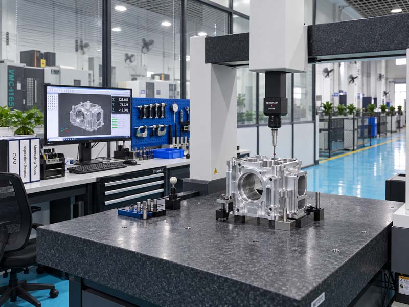
Modern CNC machines can routinely hold tolerances of ±0.005 inches (0.127 mm) for general milling, while tight tolerances down to ±0.0005 inches (0.0127 mm) are achievable with specialized setups and skilled operators. However, specifying unnecessarily tight tolerances increases manufacturing time, scrap rates, and inspection costs.
Standard Tolerance Grades and Their Applications
Internationally, tolerance grades are defined by standards such as ISO 2768 (for linear dimensions) and ISO 286 (for fits). These standards provide a systematic way to assign tolerances based on the size of the feature and the desired level of precision. Common grades include:
- Fine (f): For fits requiring high precision, e.g., bearing seats, shafts in rotating assemblies. Typical range ±0.01–0.05 mm.
- Medium (m): For general engineering parts, e.g., enclosures, brackets, housings. Typical range ±0.05–0.2 mm.
- Coarse (c): For non-critical features, e.g., rough weldments, clearance holes. Typical range ±0.2–0.5 mm.
Selecting the Right Grade
When designing a part, consider the functional requirement: does the feature need to slide, press fit, or simply clear another part? If a screw head needs to sit flush, the counterbore depth may require a tighter tolerance than a through hole for a bolt. Use the standard tables to avoid over-specification.
Factors Affecting Achievable Tolerances in CNC Machining
Several factors determine the precision a CNC shop can consistently achieve:
- Machine Tool Capability: High-end 5-axis machines with linear feedback scales can hold tighter tolerances than older 3-axis mills. Regular calibration is essential.
- Material Properties: Aluminum alloys (e.g., 6061, 7075) machine easily with minimal distortion. Stainless steels (e.g., 304, 316) work harden and require careful feed rates. Plastics (e.g., Delrin, Nylon) tend to deflect under cutting forces, leading to size variation.
- Tooling and Tool Wear: Sharp tools reduce cutting forces and improve finish. Worn tools cause oversizing or undersizing, especially on long runs.
- Workholding and Fixturing: A rigid fixture with proper clamping prevents part movement. For tight tolerances, operators may use zero-point clamping or custom jigs.
- Thermal Effects: Both the machine and the part expand with heat. Cutting fluid, temperature-controlled shops, and strategic dwell times help maintain consistency.
Geometric Dimensioning and Tolerancing (GD&T)
While traditional +/- tolerances work for simple features, GD&T offers a more robust system for controlling form, orientation, and location. Key GD&T symbols include:
- Flatness: How flat a surface must be, independent of size.
- Parallelism: How parallel two surfaces are.
- Position: The exact location of a feature relative to a datum.
- Concentricity: The coaxial alignment of rotated features.
Using GD&T clarifies design intent and often allows larger tolerances than coordinate dimensioning because it separates size from geometry. This can reduce manufacturing cost without sacrificing function.
Inspecting Tolerances: Methods and Tools
Verification is a critical step. Common inspection tools include:
- Calipers and Micrometers: For quick measurement of external lengths, diameters, and thicknesses. Typical accuracy ±0.01 mm.
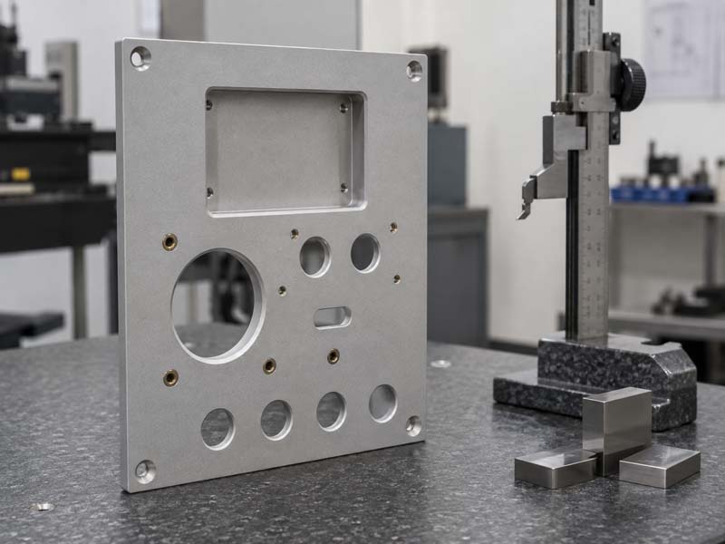
- Height Gauges and Dial Indicators: For measuring features relative to a surface plate.
- CMM (Coordinate Measuring Machines): For complex 3D geometries and GD&T verification. CMMs can achieve micron-level accuracy.
- Go/No-Go Gages: For fast pass/fail checks of holes and threaded features.
Cost Implications of Tight Tolerances
There is a direct relationship between tolerance tightness and cost. A part requiring ±0.001 inches may cost 2-3 times more than one with ±0.005 inches for the same geometry. The cost drivers include:
- Slower cutting speeds and lighter cuts
- More frequent tool changes and offsets
- Multiple inspection points and dimensional reporting
- Higher setup time and need for skilled operators
- Increased scrap risk
To optimize cost, apply tight tolerances only where function demands it. Use coarse or medium grades for non-critical surfaces, and mark Datum features clearly on the drawing.
Common Tolerance Issues and How to Avoid Them
- Stack-up: Accumulation of tolerances in an assembly can cause misalignment. Use tolerance analysis or worst-case calculations early in the design.
- Overly tight on non-functional features: This wastes money. If a pocket only holds a PCB with generous clearance, a ±0.2 mm tolerance is sufficient.
- Missing datum references: Without a clear coordinate system, the machinist may interpret the drawing differently. Always specify a consistent datum structure.
- Ignoring material springback: Thin-walled parts in resilient materials may distort after machining. Consider stress-relief or leaving stock for a finish pass.
Practical Tips for Designers
- Communicate with your CNC shop early. They can advise on achievable tolerances based on their equipment and experience.
- Use standard tolerance values from ISO 2768 or ASME Y14.5 to reduce confusion.
- For critical fits, provide both nominal dimensions and tolerances; don't rely on a single number.
- Consider adding dimension callouts for inspection features like surface plates or gauge holes.
- If you require a statistical process control (SPC) report, specify it in the purchase order.
Conclusion
CNC machining tolerances are a fundamental tool for communicating design requirements. By understanding the grades, the factors that influence precision, and the cost drivers, engineers and designers can create robust parts that perform reliably while keeping manufacturing costs manageable. Partnering with an experienced CNC shop like Hongke CNC—equipped with modern machinery and skilled technicians—ensures that your tolerances are met consistently. Start your next project with a clear tolerance strategy, and you'll save time, money, and headaches.