Introduction: Why Tolerances Matter in CNC Machining
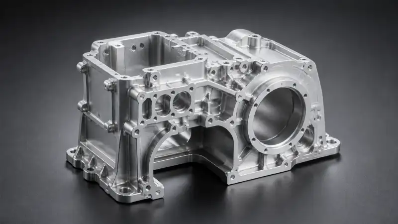
In CNC machining, tolerances define the allowable variation in a part's dimensions. They are the backbone of quality, interchangeability, and assembly reliability. Whether you're designing a simple bracket or a complex precision housing, understanding tolerances ensures your parts will fit and function as intended. This guide explains the fundamentals of CNC machining tolerances, standard grades, how to specify them on drawings, and the key factors that influence achievable precision.
What Are CNC Machining Tolerances?
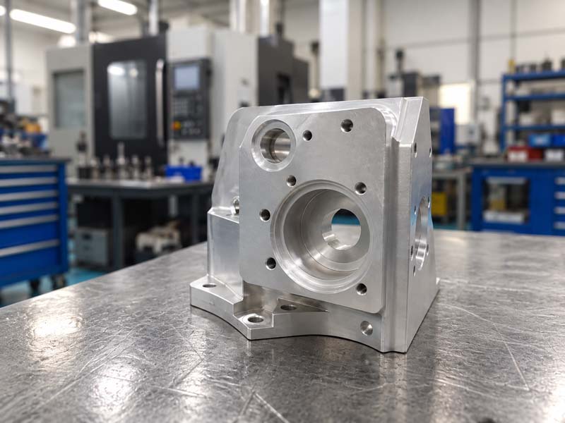
A tolerance is the total permissible deviation from a specified nominal dimension. For example, a shaft diameter of 20 mm with a tolerance of ±0.05 mm can vary between 19.95 mm and 20.05 mm. Tolerances are expressed in two common ways:
- Unilateral tolerances: Deviation in only one direction (e.g., +0.00 / -0.10).
- Bilateral tolerances: Symmetrical deviation (e.g., ±0.05).
Tolerances are directly linked to part function: tighter tolerances cost more to manufacture due to greater precision requirements, inspection, and potential scrap. Conversely, looser tolerances reduce cost but may compromise fit or performance.
Standard Tolerance Grades in CNC Machining
Internationally, ISO 2768 and ANSI/ASME Y14.5 are common standards for defining general tolerances. For machined parts, ISO 286 establishes tolerance grades (IT grades) from IT01 (extremely precise) to IT18 (very coarse). Typical CNC machining capabilities fall between IT6 and IT10:
| IT Grade | Typical Application | Approximate Tolerance Range (for 10–50 mm) |
|---|---|---|
| IT6 | Precision fits, bearings, gears | ±0.005 – 0.010 mm |
| IT7 | General engineering, shafts and holes | ±0.010 – 0.020 mm |
| IT8 | Standard assembly parts | ±0.020 – 0.040 mm |
| IT9 | Less critical dimensions | ±0.040 – 0.080 mm |
| IT10 | Coarse tolerances, non-functional surfaces | ±0.080 – 0.120 mm |
Most CNC machine shops can routinely hold tolerances of ±0.025 mm (0.001 inch) on 3-axis machines, and tighter to ±0.005 mm (0.0002 inch) with advanced equipment and careful process control.
How to Specify Tolerances in Engineering Drawings
When creating a drawing for CNC machining, follow these best practices:
- State the standard: Include a note like "General tolerances per ISO 2768-m" or "Tolerances ±0.1 mm unless noted."
- Use dimension tolerances: Write callouts like "20 ±0.05" or "10 H7/g6" for fits.
- Geometric dimensioning and tolerancing (GD&T): For critical features, use GD&T symbols (e.g., flatness, parallelism, position) to control form and location.
- Avoid over-tolerancing: Only tighten tolerances where necessary for function or assembly. Unnecessarily tight tolerances increase cost and lead time.
Common Fit Types: Clearance, Transition, Interference
When designing parts that mate together (e.g., a shaft in a bore), you must specify a fit. The most common system is the Hole Basis System (preferred) or Shaft Basis System. Three basic fit categories exist:
- Clearance fit: The shaft is always smaller than the hole (e.g., H7/g6 for sliding fits).
- Transition fit: The shaft may be slightly larger or smaller (e.g., H7/k6 for locating fits).
- Interference fit: The shaft is always larger than the hole, requiring press assembly (e.g., H7/p6 for permanent assembly).
Each fit has a range of possible clearances or interferences defined by the tolerance zones. The ISO system uses letter-number codes: uppercase for holes, lowercase for shafts. For example, "40 H7 g6" means a 40 mm hole with tolerance zone H7 and a shaft with g6.
Factors That Affect Achievable Tolerances
Several factors influence how tight a tolerance a CNC machine can hold:
- Machine rigidity and condition: Older or less rigid machines may struggle with tight tolerances on heavy cuts.
- Cutting tool wear: Tools wear during production, gradually changing dimensions. Regular tool offset compensation is required.
- Material properties: Harder materials (e.g., stainless steel, titanium) cause more tool deflection and thermal expansion than aluminum or plastics.
- Thermal effects: Heat from cutting and ambient temperature changes can expand the part or machine. Temperature-controlled shops are essential for sub‑micron tolerances.
- Workholding stability: Poor fixturing leads to vibration and movement, reducing dimensional accuracy.
- Number of setups: Parts requiring multiple setups carry higher cumulative positioning errors. Consider using 5‑axis machining or custom fixtures to reduce setups.
Cost vs. Tolerance: The 80/20 Rule
In CNC machining, the relationship between tolerance and cost is exponential. Relaxing a tolerance from ±0.05 mm to ±0.1 mm can reduce machining time by 30–50% and inspection cost significantly. Tight tolerances require slower feeds, smaller depth of cut, frequent tool changes, and often secondary finishing operations. Always follow the principle: specify the loosest tolerance that still meets functional requirements.
Inspection Methods for Verifying Tolerances
To ensure parts meet specified tolerances, shops use various inspection tools:
- Calipers and micrometers: For linear dimensions (accuracy ±0.02 mm).
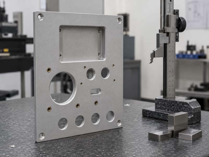
- Height gauges and bore gauges: For internal/external measurements.
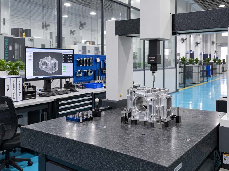
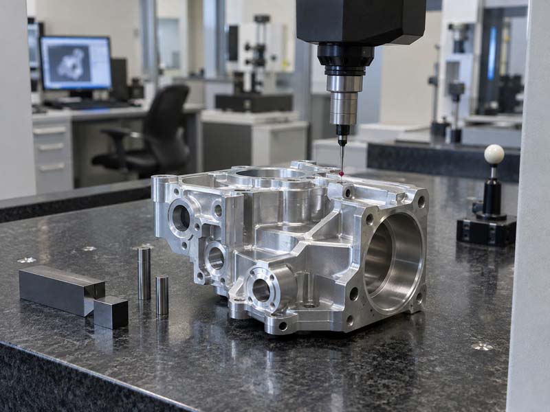
- CMM (Coordinate Measuring Machine): For 3D measurements with high accuracy (±0.001 mm).
- Go/No‑go gauges: For feature acceptance (e.g., thread gauges).
Hongke CNC, for example, uses CMM inspection and precision gauges as seen in their quality control processes, ensuring consistent adherence to customer specifications.
Best Practices for Engineers
- Communicate with your machining partner early about critical dimensions.
- Provide a clear drawing with tolerances explicitly stated; use GD&T for complex relationships.
- Avoid unnecessary surface finish requirements that indirectly tighten tolerances.
- Consider tolerance stack-up analysis for assemblies.
- Use standard fits (H7/g6, H7/p6) whenever possible to reduce special tooling and gauging.
Conclusion
Mastering CNC machining tolerances is essential for designing parts that are functional, manufacturable, and cost-effective. By choosing appropriate tolerance grades, specifying fits correctly, and factoring in machine and material limits, you can achieve reliable precision while controlling production costs. Whether you are prototyping or mass-producing, a solid understanding of tolerances will help you get better results from your CNC machining partner.