Introduction
In precision CNC machining, achieving the correct tolerances and surface finishes is critical for part functionality, assembly, and appearance. Whether you are designing a bracket, housing, or manifold block, understanding how to specify these requirements on your engineering drawings will reduce costs, lead times, and scrap. This guide provides engineers with a clear overview of common tolerance standards, surface roughness parameters, finishing options, and inspection methods used in modern CNC shops.
Why Tolerances and Surface Finishes Matter
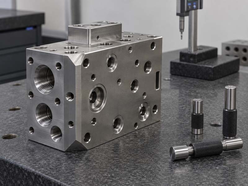
Tolerances define the permissible variation in a part's dimensions. Without them, parts may not fit together, seals may leak, or moving components may bind. Surface finish affects friction, wear, electrical conductivity, and aesthetics. For example, a hydraulic manifold block requires tight tolerances on port threads and a smooth sealing surface (often 0.8 μm Ra or better) to prevent fluid leakage. Conversely, a non-functional outer surface may only need a standard machined finish (3.2 μm Ra).
Common Tolerance Standards in CNC Machining
The most widely used standard is ISO 2768, which provides general tolerances for linear and angular dimensions without individual tolerance indications. Under ISO 2768-m (medium class), for nominal dimensions up to 120 mm, the tolerance is ±0.1 mm. For tighter control, engineers specify exact tolerances like ±0.05 mm or ±0.025 mm (typical for precision CNC). Another common standard is ASME Y14.5 for geometric dimensioning and tolerancing (GD&T), which defines form, orientation, and runout controls.
When designing parts for CNC machining, avoid over-specifying tolerances. Every additional 0.01 mm of tightness can increase machining cost by 10–30%. Apply tight tolerances only to critical mating surfaces and functional features (bores, shaft fits, pin holes). Use standard tolerances for non-critical dimensions (cast surfaces, fastener clearance holes).
Practical Tolerance Ranges for Aluminum Parts
- Standard (ISO 2768-m): ±0.1 mm for dimensions up to 120 mm. Suitable for clearance fit holes, general profiles.
- Precision (∼±0.05 mm): Common for bearing housings, locating features, and press-fit diameters.
- High Precision (∼±0.025 mm or tighter): Required for interlocking parts, seal grooves, and high-speed rotating assemblies. Note: possible only with post-machining grinding or lapping.
Surface Finish Parameters (Ra, Rz, and More)
The most common parameter is Ra (average roughness), measured in micrometers (μm). A typical as-machined surface from milling or turning with a sharp insert yields Ra 1.6 μm to 3.2 μm. Finer finishes require special toolpaths, wiper inserts, or secondary processes.
| Ra Value (μm) | Typical Process | Application Example |
|---|---|---|
| 0.4 – 0.8 | Grinding, polishing, or fine boring | Sealing faces, bearing journals |
| 0.8 – 1.6 | Precision milling/turning with wiper inserts | Hydraulic valve bores, mating surfaces |
| 1.6 – 3.2 | Standard CNC milling/turning | General functional surfaces, mounting faces |
| 3.2 – 6.3 | Coarse milling or sand-cast finish | Non-critical areas, aesthetic surfaces |
It is important to note that specifying a very fine finish (e.g., Ra 0.4 μm) on a large aluminum part can significantly increase cost. Designers should choose the loosest finish that still meets functional requirements.
Surface Finishes for CNC Parts: Options and Comparisons
After machining, parts can be left as-machined or receive additional surface treatments. Common options include:
- As Machined (Natural): Visible tool marks, average Ra 1.6–3.2 μm. Lowest cost. Suitable if function is more important than appearance.
- Bead Blasting: Produces a uniform matte texture, typically Ra 2.0–3.0 μm after blasting. Hides minor scratches and tool marks. Common for enclosures and consumer products.
- Anodizing (Type II or Type III): Adds a protective oxide layer. Anodizing does not significantly change surface roughness unless applied thick (hard anodize may increase Ra by 0.2–0.5 μm). Color options available.
- Powder Coating: Adds a thick (60–150 μm) layer, covering up to Ra 6.3 μm. Provides excellent corrosion resistance and color variety, but may affect tight tolerances on mating surfaces. Masking required.
- Plating (Nickel, Chrome, etc.): Thin metal deposit (0.005–0.050 mm). Can improve conductivity, wear resistance, and solderability. Usually applied to steel or brass.
When specifying a surface finish, always consider post-treatment dimensional changes. For example, anodizing adds 5–10 μm per side (Type II) or up to 50 μm (Type III hard coat). If tight tolerances are required on anodized surfaces, machine the part undersized and then anodize, or machine after anodizing (carefully).
Inspection Methods for Tolerances and Surface Finish
To verify that parts meet specifications, CNC shops use various inspection equipment:
Dimensional Measurement
- Calipers and Micrometers: Quick checks for internal/external dimensions, outside diameters, and thickness. Accuracy to ±0.01 mm.
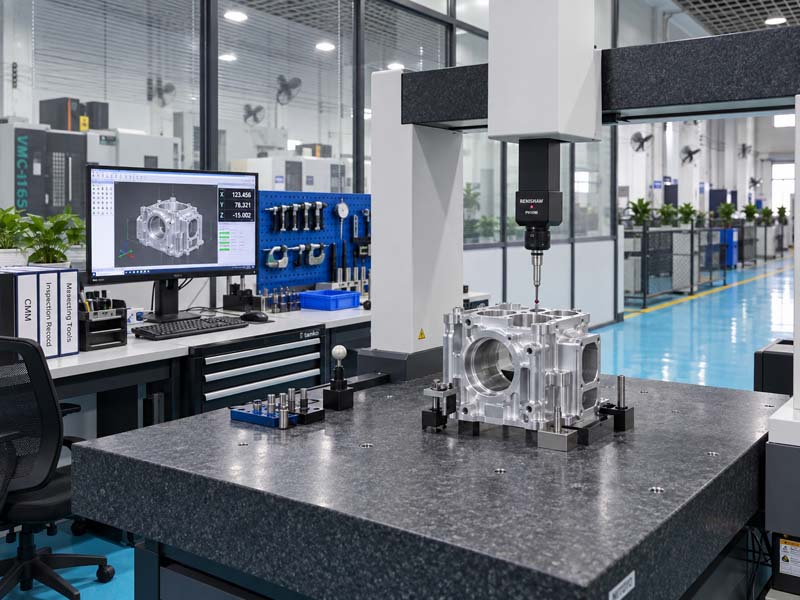
- CMM (Coordinate Measuring Machine): Using a touch probe, CMM measures complex geometries, bores, and true positions with high accuracy (typically ±0.005 mm). Ideal for GD&T verification.
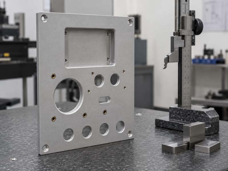
- Height Gauge / Surface Plate: For flatness, parallelism, and height dimensions. Common for inspection of flanges and panels.
Image: Height gauge inspection of an aluminum front panel.
Surface Roughness Measurement
- Contact Profilometer: A stylus traverses the surface and records Ra, Rz, etc. Typically used for Ra 0.1–6.3 μm ranges. Required for parts with explicit roughness callouts.
- Optical Profilometer (Non-contact): Faster and can measure softer materials without scratching. Used for complex surfaces like impellers or curvature.
For many shops, process capability is well-established; for example, a standard CNC milling operation with a 4-flute end mill at 0.05 mm/rev feed typically produces Ra 1.8–2.5 μm. Deviation from this may indicate tool wear or vibration.
Thread and Port Inspection
For parts with threaded holes (e.g., manifold blocks), thread gauges (GO/NO-GO) and thread micrometers ensure pitch diameter and depth are correct. Visual inspection with a borescope may also be used for internal threads.
Design for Machining (DFM) Tips to Optimize Tolerances and Finishes
- Limit the number of tight tolerance features: Concentrate tight tolerances on critical mating surfaces. Use general tolerances elsewhere.
- Avoid sharp internal corners: Internal radii should be at least 1/3 of the tool diameter to prevent excessive tool wear and poor finish. Specify a radius (e.g., R2) instead of a sharp corner.
- Design for uniform material removal: Avoid heavy cuts that cause vibration. If possible, keep wall thickness uniform to reduce distortion.
- Choose appropriate material: Aluminum 6061-T6 machines well and holds tight tolerances. Stainless steel 304 requires slower speeds and may work-harden. Brass is free-machining.
- Consider post-machining stress relief: For complex aluminum parts, stress-relief annealing after roughing can minimize distortion during finishing.
- Surface finish callouts on drawings: Use standard symbols per ISO 1302 or ASME Y14.36. Indicate the Ra value and any direction of lay (perpendicular, parallel, etc.).
Conclusion
Mastering tolerances and surface finishes in CNC machining is essential for producing reliable, cost-effective parts. By understanding standard tolerance classes, surface roughness parameters, finishing options, and inspection methods, engineers can effectively communicate requirements to Hongke CNC or any precision machine shop. Always remember: specify only what is needed, avoid over-engineering, and collaborate with your machining partner early in the design phase. This approach will save time, money, and ensure your parts perform as intended.