
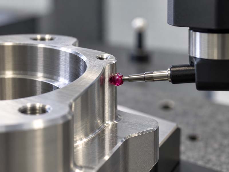
A CNC drawing may look simple, but a few design details can make the part much more difficult to machine. Deep pockets, unnecessarily tight tolerances, thin walls and inaccessible internal corners can increase setup time, tool deflection and inspection requirements.
One of the most common areas where design intent and manufacturing reality diverge is tolerance. Many drawings specify tolerances that are far tighter than the part's function requires. This adds cost, increases lead time, and can lead to unnecessary scrap without improving performance.
This guide explains CNC machining tolerances from both an engineering and a procurement perspective. It covers standard achievable tolerance ranges, the factors that affect precision, how to specify tolerances on a drawing, and how to avoid over-tolerancing.
What Is a Realistic CNC Machining Tolerance?
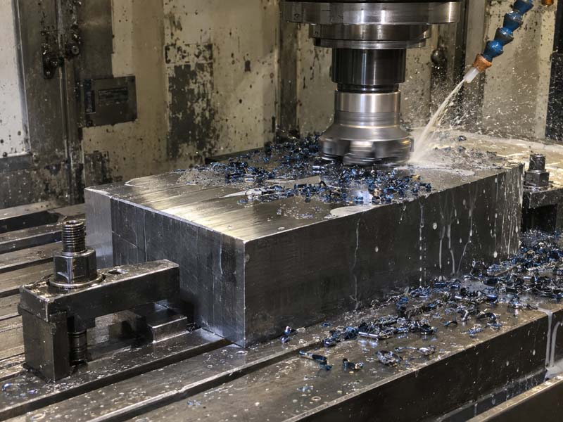
CNC machining is a subtractive process where a rotating cutting tool removes material from a solid block. The accuracy of the final part depends on the machine, the tool, the workholding, the material, and the operator's skill.
In standard practice, a typical CNC milling or turning operation can hold linear dimensions to:
±0.005 inches (±0.125 mm) for most features without special effort.
±0.002 inches (±0.05 mm) with careful setup and standard tooling.
±0.001 inches (±0.025 mm) or tighter if the geometry, material, and machine permit.
It is important to understand that these values are general industry references. The actual achievable tolerance for a specific part depends on several variables, which we will discuss in detail.
A more practical approach is to use the following classification when reviewing a drawing:
- Standard tolerance (coarse or general): ±0.005 in / ±0.125 mm. Suitable for most non-critical dimensions.
- Fine tolerance: ±0.002 in / ±0.05 mm. Requires moderate control over setup and tool condition.
- Precision tolerance: ±0.001 in / ±0.025 mm or tighter. Requires stable machines, temperature control, and often specialized tooling and inspection.
Factors That Affect CNC Machining Tolerance
No machine holds the same tolerance on every feature of every part. The following factors directly influence whether a tolerance can be achieved reliably.
Part Geometry and Feature Accessibility
If a critical dimension requires a long reach, the tool must be extended. Longer tools deflect more under cutting force. A deep pocket, a thin wall, or an internal corner with a small radius can all force the use of a longer tool, reducing accuracy.
For example, a hole depth that is five times the tool diameter will typically allow less positional accuracy than a shallow hole of the same diameter. The tool will deflect, and the hole may become slightly tapered or out of position.
Material Machinability
Materials that are soft, gummy, or highly abrasive can affect tolerance. Aluminum 6061 is generally stable and easy to machine to tight tolerances. Stainless steel 304 work-hardens and can cause tool deflection. Plastics may soften from heat and deform during cutting.
Thermal expansion is also a factor. A part made from aluminum that is milled at 25°C and measured at 20°C will shrink by approximately 0.002 mm per 100 mm per degree Celsius. This can be significant for tight tolerance features.
Workholding and Fixturing
The way a part is held directly affects how accurately it can be machined. A thin-walled part clamped in a vise may distort when the clamp is released. A part that requires multiple setups to access all features will accumulate positional error from one setup to the next.
A fixture plate with locating pins and clamps provides better repeatability than a general-purpose vise for batch production, but the fixture design itself must be rigid enough to withstand cutting forces.
Machine Condition and Tool Wear
A well-maintained CNC machine with a rigid spindle and high-quality linear guides can hold tighter tolerances consistently. As tools wear, the cutting edge changes, and the force on the tool increases. This can cause the tool to deflect or the surface finish to degrade, affecting dimensional accuracy.
For tight tolerance features, the operator must monitor tool wear and replace the tool before it degrades the part. This adds inspection steps and tooling cost.
Thermal Stability of the Machine and Shop
CNC machines generate heat during operation. Spindle rotation, axis movement, and cutting all add heat. If the machine is not thermally stable, the spindle may grow relative to the table, changing the effective tool length and affecting Z-axis depth.
In a shop without climate control, a part machined in the morning and measured in the afternoon may show different dimensions. For tight tolerance work, temperature-controlled environments and machine warm-up routines are necessary.
How to Specify Tolerances on a CNC Machining Drawing
A well-prepared drawing communicates the engineer's intent clearly. The following practices help avoid confusion and unnecessary cost.
Use a General Tolerance Block
Many drawings use a general tolerance block that applies to unmarked dimensions. A typical block might be:
UNLESS OTHERWISE SPECIFIED:
DIMENSIONS IN INCHES / MILLIMETERS
X.XX = ±0.010 in / ±0.25 mm
X.XXX = ±0.005 in / ±0.125 mm
ANGLES = ±0.5°
This approach reduces the number of individual tolerance callouts and provides a clear baseline for the machinist. Only dimensions that require tighter control should be called out separately.
Avoid Over-Tolerancing Non-Critical Features
If a dimension is not functionally critical, leave it at the standard tolerance. Every additional decimal place or tighter callout adds setup time, tool change frequency, and inspection cost. A common mistake is to specify ±0.001 in on all dimensions of a part when only one or two features require that precision.
For example, a mounting hole location that aligns with another part may need a tight positional tolerance. The overall length of the same part, which is non-functional, can use the general tolerance block.
Use GD&T for Functional Requirements
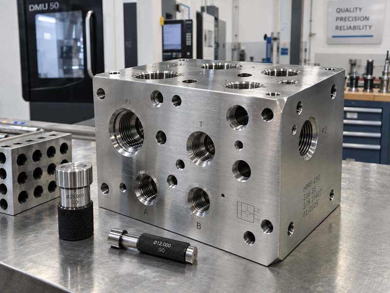
Geometric Dimensioning and Tolerancing (GD&T) provides a more precise way to define the allowable variation in form, orientation, and location. Instead of relying solely on linear tolerances, GD&T allows the engineer to define a tolerance zone for the feature.
For example, a flatness callout of 0.05 mm on a sealing surface communicates the requirement clearly. A position tolerance of 0.1 mm to a datum for a bolt hole pattern ensures the holes will align with mating parts.
GD&T is particularly useful for parts that require assembly or that have multiple critical features. It reduces ambiguity and helps the machinist understand which features are truly critical.
Include Critical Dimensions in a Table
For parts with many critical features, a table of critical dimensions with specific tolerances is more effective than scattering callouts across the drawing. The machinist can quickly identify which features require extra attention, and the inspector can verify them efficiently.
This method also reduces the risk of a dimension being overlooked during programming or setup.
The Cost of Tight Tolerances in CNC Machining
There is a direct relationship between tighter tolerances and higher manufacturing cost. Understanding this relationship helps buyers and engineers make informed decisions.
Increased Setup and Inspection Time
To hold ±0.001 in, the operator may need to indicate the workpiece more carefully, use a specialized workholding fixture, and probe the part during machining. After machining, the part must be inspected with a CMM or precision gauges, which adds time.
For a batch of 500 parts, an extra two minutes of inspection per part adds nearly 17 hours of inspection time.
More Frequent Tool Changes
A tool that can cut 200 parts to a ±0.005 in tolerance may need to be replaced after 80 parts to maintain ±0.001 in. The cost of the tool and the downtime for tool change are both higher.
Higher Scrap Risk
Tight tolerance parts are more likely to be out of tolerance if a setup shifts, a tool wears, or the material has internal stresses. The risk of scrapping a part that has already consumed machine time and material is higher. This risk is reflected in the price.
Reduced Process Flexibility
If a part requires tight tolerance features that must be machined in a single setup, the workholding becomes more complex. Fixtures may need to hold the part from multiple sides, or the part may require a 4th or 5th axis machine to avoid multiple setups.
This limits the number of machines that can run the part, potentially increasing lead time and machine rate.
When to Specify Tight Tolerances
Tight tolerances should be reserved for features that directly affect function, fit, or assembly. Examples include:
- Bearing bore diameters that must match a bearing size.
- Shaft diameters that fit into a bearing or bushing.
- Locating pin holes that align with another component.
- Sealing surfaces that require flatness or parallelism.
- Threads that must engage with a mating part to a specified depth.
All other dimensions can typically be produced at a standard tolerance without affecting the part's performance.
How to Communicate Tolerance Requirements to a Supplier
A clear drawing is the best way to communicate tolerance requirements. When requesting a CNC machining cost estimate, include a PDF of the drawing with a clear tolerance block and any critical dimensions highlighted.
If the part has GD&T callouts, confirm that the supplier has the software and equipment to interpret and inspect them. Not all shops are equipped to inspect complex GD&T requirements.
If the drawing is available as a 3D model, a STEP or IGES file is preferred for programming. The 2D drawing should still accompany the model to communicate tolerances, surface finish, and other specifications.
For parts with very tight tolerances, ask the supplier to review the drawing before quoting. A DFM (Design for Manufacturability) review can identify features that are unnecessarily tight and suggest alternatives that reduce cost without sacrificing function.
A Practical CNC Machining Tolerance Chart
The following table provides a general reference for typical achievable tolerances in standard CNC milling and turning. These are practical values for most job shops. Always confirm capability directly with the supplier for your specific part geometry and material.
| Feature Type | Typical Tolerance (Inches) | Typical Tolerance (mm) | Notes |
|---|---|---|---|
| Linear dimension (length, width, height) | ±0.005 | ±0.125 | Standard, no special effort |
| Bore diameter | ±0.001 | ±0.025 | Requires fine boring or reaming |
| Hole location | ±0.003 | ±0.075 | Positional tolerance |
| Thread pitch diameter | ±0.002 | ±0.050 | Thread class dependent |
| Flatness (reference surface) | 0.002 | 0.050 | Over 100 mm length |
| Concentricity (turned part) | 0.002 TIR | 0.050 TIR | Requires single setup |
| Surface finish (Ra) | 3.2 µm | 3.2 µm | Standard machining finish |
These values are provided as a general engineering reference. The actual achievable tolerance depends on part geometry, material, and the specific machining process used.
For example, a turned shaft with a diameter of 25 mm can typically hold ±0.025 mm in a single setup. The same bore machined on a milled part with a long end mill will be more difficult to hold to the same tolerance.
Inspection Methods for Toleranced Features
Verifying tight tolerances requires appropriate inspection equipment. For most CNC machined parts, the following methods are common:
- Calipers and micrometers: Suitable for ±0.002 in / ±0.05 mm and above.
- CMM (Coordinate Measuring Machine): Required for ±0.001 in / ±0.025 mm and for GD&T features.
- Gauge pins and plug gauges: Used for hole diameters and threads.
- Surface roughness tester: Required when a specific Ra value is called out.
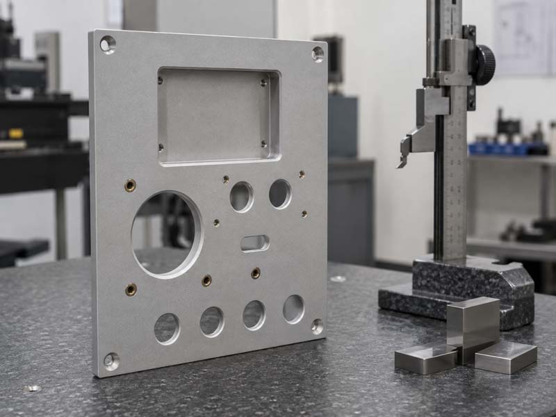
When a tolerance is critical, the drawing should specify both the requirement and the inspection method if necessary. For example, ±0.0005 in on a bore diameter cannot be verified with a standard caliper. The supplier must have a suitable gauge or CMM.
Common Questions About CNC Machining Tolerances
What is the standard tolerance for CNC machining?
Standard linear tolerances are typically ±0.005 inches (±0.125 mm) for most job shops. Many parts can be produced to ±0.002 inches without significant extra cost.
Can CNC machining hold ±0.001 inch?
Yes, but it requires a stable machine, careful setup, sharp tooling, and often temperature control. It also increases the risk of scrap and adds to the cost.
Does every dimension need a tolerance?
Yes, but most dimensions should use a general tolerance block. Only functionally critical dimensions need individual callouts.
How does part geometry affect tolerance?
Features that require long tool reach, deep pockets, or thin walls are more difficult to hold to tight tolerances. The tool will deflect more, and the part may deform.
What is the difference between unilateral and bilateral tolerance?
Bilateral tolerance allows variation in both directions from the nominal value (e.g., 25.00 ± 0.05 mm). Unilateral tolerance allows variation in only one direction (e.g., 25.00 +0.05 / -0.00 mm).
Summary for Buyers and Engineers
Specifying the right CNC machining tolerance is a balance between function and cost. A few key points to remember:
- Use a general tolerance block for most dimensions.
- Only apply tight tolerances to features that are functionally critical.
- Understand the factors that affect tolerance, such as tool reach and material.
- Communicate clearly with your supplier through a well-prepared drawing.
- Allow the supplier to review the drawing for DFM before quoting.
A well-toleranced part is not the one with the tightest numbers. It is the one where every tolerance is justified by the function, and every unnecessary decimal place has been removed.