
When you send a drawing to a CNC machining services supplier, tolerance is one of the first things the engineering team will review. Too tight, and the part becomes expensive and risky. Too loose, and the part may not assemble or function correctly. But what tolerance can CNC machining actually achieve? Which dimensions need tight control? And why does a tighter tolerance increase cost? This guide answers those questions from both an engineering and a procurement perspective.
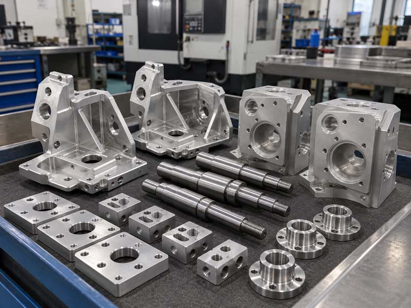
What Tolerance Can CNC Machining Achieve?
As a general reference, standard CNC machining can hold dimensional tolerances within ±0.005 inches (0.13 mm) without special effort. For applications requiring higher accuracy, precision machining can achieve ±0.002 inches (0.05 mm) or even ±0.001 inches (0.025 mm) depending on material, geometry, and machine condition.
These numbers are for reference. The actual achievable tolerance depends on several factors:
- Part material: Aluminum is more dimensionally stable than thin stainless steel sections.
- Part geometry: A simple turned shaft is easier to control than a thin-walled housing.
- Machine condition: A well-maintained CNC milling center with thermal compensation performs differently than an older machine without.
- Number of setups: Each additional setup introduces a new reference, which can stack tolerance errors.
In practice, it is common to specify ±0.005 inches for general dimensions and apply tighter tolerances only where function requires. For example, a bearing pocket might need ±0.001 inches, while an outer enclosure dimension can remain at ±0.010 inches.
Why Tight Tolerances Increase CNC Machining Cost
Every additional 0.001 inch of precision adds machining time, inspection time, and scrap risk. Understanding why helps you decide where to tighten and where to relax.
Setup and Tooling
Holding tight tolerance requires stable workholding, rigid tooling, and often multiple finishing passes. A deep pocket with a ±0.001 inch tolerance may need a semi-finish pass followed by a finish pass, doubling machining time compared to a ±0.005 inch tolerance.
Thermal Stability
When machining steel or titanium, heat buildup can cause the part to expand during cutting and contract after cooling. To maintain ±0.001 inch, the operator may need to pause between passes, flood coolant, or even let the part stabilize before final measurement. All of this adds cycle time.
Inspection Requirements
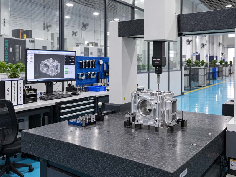
Tighter tolerances require more rigorous inspection. A ±0.001 inch dimension may require a CMM (coordinate measuring machine) check, while a ±0.010 inch dimension can be verified with a caliper. CMM inspection takes longer and may require a dedicated setup. For a batch of 50 parts, this adds measurable cost.
Scrap and Rework Risk
When a dimension is specified at the edge of machine capability, even normal tool wear can push the dimension out of tolerance. A part that is 0.001 inch oversize may be scrapped if the tolerance is ±0.0005 inch, whereas the same deviation would be acceptable under ±0.005 inch. Higher scrap risk is factored into the quote.
When Is Tight Tolerance Actually Necessary?
Not every dimension on a drawing needs a tight tolerance. Good design for manufacturability (DFM) means reserving tight tolerances for functional surfaces and letting everything else relax.
Typical cases that justify tighter control include:
- Bearing fits: A bearing bore typically needs H7 fit, which is approximately +0.000 to +0.001 inches depending on diameter.
- Press-fit assemblies: Shaft-to-hole interference fits require tight control to achieve the correct insertion force without damaging the parts.
- Sealing surfaces: Where an O-ring or gasket must seal, flatness and surface roughness become critical.
- Alignment features: Dowel pin holes or locating slots that position two components relative to each other.
- Thread pitch diameters: For threaded assemblies that must engage smoothly, especially in stainless steel or titanium.

Example: Saving Cost by Relaxing Non-Critical Tolerances
Consider a custom machined part that is a rectangular aluminum housing with a bearing bore and four mounting holes. A drawing might specify ±0.005 inches for all dimensions. In reality, only the bearing bore and the hole-to-hole center distances for the mounting holes are functionally critical. The overall length, width, and height of the housing, if relaxed to ±0.010 inches, would not affect assembly. This change can reduce machining and inspection time by 15–20 percent.
How to Specify Tolerances on Your Drawing
The drawing is the contract between your design and the machinist. Clear tolerance specification reduces back-and-forth and ensures the part meets your requirements.
Use a Standard Tolerance Block
Most drawings include a general tolerance block in the title block or notes section. A common approach is:
- ±0.005 inches for three decimal place dimensions
- ±0.010 inches for two decimal place dimensions
- ±1/64 inch for fractional dimensions
Then, apply tighter tolerances only to specific dimensions that need them, using direct callouts on the dimension line. This prevents over-tolerancing the entire part.
Specify Geometric Tolerances (GD&T) for Complex Requirements
For features where position, flatness, or concentricity matters more than size alone, use geometric dimensioning and tolerancing (GD&T). For example:
- True position: Controls the location of a hole pattern relative to a datum, even if the holes are slightly oversize.
- Flatness: For sealing surfaces, flatness tolerance is often tighter than the size tolerance.
- Concentricity: For turned parts that must rotate without wobble.
Drawing review service before quoting can identify tolerance specification errors that lead to high quotes or production issues.
Avoid Unnecessary Stack-Up
When multiple dimensions on a drawing reference different datums, the tolerance stack-up can become larger than intended. For example, if a hole position is dimensioned from two separate edges, the tolerance on both edges adds up. Instead, use a single datum reference to minimize stack.
Common Tolerance Mistakes in RFQs
During procurement evaluation, suppliers frequently see these issues:
Over-Tolerancing by Habit
Some drawings specify ±0.005 inches on every dimension because that is what the CAD template uses. This drives up cost unnecessarily without any functional benefit.
Missing GDT References
A dimension with a ±0.001 inch tolerance but no datum reference leaves the machinist guessing which surface to measure from. This can lead to a part that passes inspection but does not assemble with other components.
Ignoring Material Effects
A thin-walled part in plastic will deflect more than the same design in aluminum. Specifying ±0.002 inches on a thin nylon bracket is unrealistic, because the material itself will expand and contract beyond that range during operation.
How a Supplier Should Evaluate Tolerance Requirements
When you send an RFQ to a precision CNC machining manufacturer, a responsible engineering team will review the drawing and flag tolerance issues before quoting. Here is what they should consider:
- Is the tolerance achievable with the planned process? For example, a deep hole on a 4-axis machine may need a custom long-reach tool, which affects tolerance.
- Does the tolerance align with the datum structure? If the drawing references a datum that cannot be machined in the same setup, tolerance stack may occur.
- Are the tolerances compatible with the material? Some aluminum grades are easier to hold tight tolerances than stainless steel or titanium, which generate more heat during cutting.
- Does the tolerance increase the number of setups? A critical tolerance that requires cutting two surfaces in the same setup may force a more complex workholding arrangement.
A supplier that provides CNC machining quote without reviewing the drawing is not giving you an accurate assessment. Always choose a partner who engineers the process, not just produces chips.
How to Reduce CNC Machining Cost Through Tolerance Strategy
If your goal is to lower part cost without sacrificing function, here is the most effective approach:
- Identify the critical dimensions. Only 10–20 percent of dimensions typically require tight control.
- Use a standard tolerance block for all others. This communicates to the machinist that those dimensions are not critical.
- Specify GD&T for positional requirements rather than applying a tight linear tolerance across multiple dimensions.
- Ask your supplier for a DFM review. An experienced machining team can suggest where tolerances can be relaxed.
- Consider the production quantity. For a prototype run of 5 parts, it may be acceptable to pay for tighter all-around tolerance. For a production run of 500 parts, relaxing non-critical tolerances adds up quickly.
A well-prepared drawing and a clear understanding of tolerance give you a better custom CNC parts experience: lower cost, fewer engineering changes, and faster delivery.