
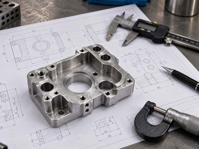
Why Thin-Wall Parts Are Difficult to Machine
Thin-wall components are among the most frequently discussed challenges in precision CNC machining. When the wall thickness falls below a certain threshold relative to the part's overall size, the structure loses rigidity. During machining, cutting forces easily overcome the material's local stiffness, causing the wall to deflect, vibrate, or even permanently deform.
This behavior is not a machine problem. It is a physics problem. Even a rigid 5-axis machine tool cannot prevent a thin wall from moving if the cutting force exceeds the local support. Understanding the relationship between wall thickness, material properties, tool engagement, and workholding is essential to producing thin-wall parts within tolerance.
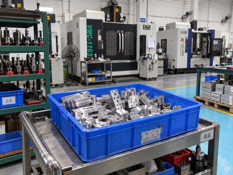
Key Factors That Influence Thin-Wall Machining Stability
Wall Thickness and Part Geometry
The most obvious factor is wall thickness. As a general engineering reference, walls below 1.5 mm in aluminum or 1.0 mm in steel often require special attention. However, a thin wall attached to a thick base may behave differently from a thin wall that is free-standing on both sides. The ratio of wall height to thickness (slenderness ratio) is more predictive than absolute thickness. A 1.0 mm wall that is 50 mm tall will deflect far more than the same thickness with a height of 10 mm.
Material Machinability and Hardness
Soft, ductile materials like 6061 aluminum or low-carbon steel are more prone to deformation because they allow plastic flow under cutting pressure. Harder materials such as stainless steel or titanium can be more stable per unit thickness, but they generate higher cutting forces, which can push the wall beyond its yield point. Heat generation also matters. Materials like stainless steel retain heat, which can cause thermal expansion and subsequent distortion when the part cools.
Cutting Tool Geometry and Engagement
Using a large-diameter cutter with a small radial engagement (high radial depth, low axial depth) is a common strategy to reduce deflection forces. The tool's cutting edge geometry, such as helix angle and rake angle, affects the direction of cutting forces. A high-helix endmill reduces radial forces but increases axial forces. For thin walls, the radial force is what pushes the wall sideways, so minimizing radial force is beneficial.
Workholding and Fixturing
Thin-wall parts require workholding that provides maximum support without inducing distortion from clamping pressure. Vacuum fixtures, soft jaws, custom fixtures with back-up supports, and even adhesive mounting are used. The clamping sequence matters. Clamping a thin part on its thickest section first, then machining the thin sections last, can prevent stress buildup.
Common Defects in Thin-Wall CNC Machining
- Wall bulging or concavity: Result of material spring-back after tool passes. Often appears on opposite side of cut.
- Chatter marks: Regenerative vibration between tool and workpiece. Shows as visible waves on surface.
- Dimensional deviation: Wall thickness measures less or more than specified due to deflection during machining.
- Burr formation: Thin edges deform easily, creating large burrs on exit side.
- Local overheating and discoloration: Insufficient chip evacuation in deep thin-walled pockets.
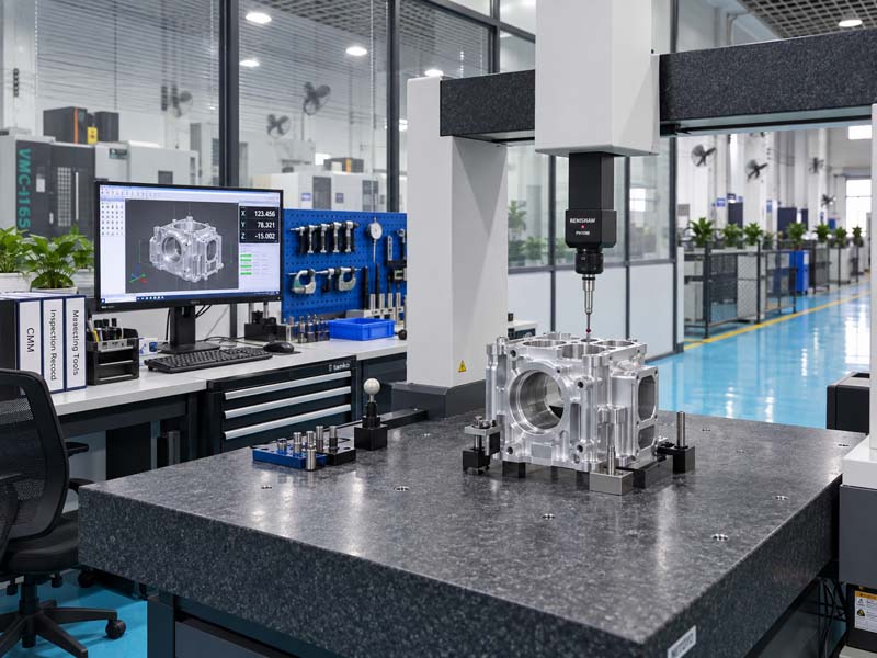
Engineering Solutions for Machining Thin-Wall Parts
1. Optimize Cutting Strategy
Use trochoidal milling or adaptive clearing toolpaths that maintain a constant chip load and reduced radial engagement. This spreads the cutting force over a longer tool path and avoids sudden force spikes. For finishing passes, take light radial depths (0.1–0.5 mm) with multiple passes rather than one heavy pass.
2. Reduce Tool Runout and Increase Tool Rigidity
Use a precision collet or shrink-fit holder. Minimize tool overhang. For deep thin-wall pockets, consider using a shorter tool with a larger shank diameter. If long reach is necessary, use a tool with vibration-damping geometry or carbide material to reduce deflection.
3. Support the Thin Wall During Machining
Use potting (low-melt alloy or wax) to temporarily fill thin-walled cavities, providing internal support. After machining, the support material is melted or washed out. Alternatively, use custom soft jaws that contour to the part shape, or vacuum fixtures that hold the part uniformly across its surface.
4. Manage Clamping and Stress Relief
Avoid over-clamping that distorts the part before cutting. Use torque-limiting wrenches on fixture bolts. For large thin-wall parts, consider rough machining first, then stress relief (e.g., cryogenic treatment or vibratory stress relief), followed by finish machining. This approach is common in aerospace thin-wall components.
5. Adjust Cooling and Chip Evacuation
Flood coolant can push thin walls and cause thermal shock. Use mist or air blast for cooling and chip removal. High-pressure coolant through the tool can help clear chips from deep pockets without applying lateral force on the wall.
Design for Manufacturability: Thin-Wall Parts
Designers can significantly reduce machining difficulty by following a few principles:
- Avoid uniform thin walls across a large area. Introduce ribs, gussets, or local thickening to break up large unsupported spans.
- Increase wall thickness at the base where stresses concentrate.
- Add fillets at internal corners to reduce stress concentration and improve tool access.
- Specify realistic tolerances. A thin wall may not hold the same tolerance as a solid boss. Communicate which surfaces are truly functional.
- Consider using a stiffer material if design permits (e.g., 7075 aluminum vs 6061).
How Thin-Wall Complexity Affects Machining Cost and Lead Time
Thin-wall parts often require multiple setups, specialized fixtures, slower feed rates, and extra inspection steps. All of these increase machining time and cost. If a thin-wall feature is not functionally critical, simplifying the design or relaxing the tolerance can reduce cost significantly. For example, increasing a wall from 1.0 mm to 1.5 mm may cut cycle time by half due to fewer finishing passes and less need for secondary operations.
When requesting a quotation from a precision CNC machining supplier, provide the following additional information for thin-wall parts:
- Indicate which walls are thin and their height.
- Specify the critical dimensions and tolerances allowed.
- Mention if full wall thickness must be measured after machining.
- Clarify if the part is subject to thermal or vibration environment in its final use.
- Share any prototype experience with similar geometries.
Summary of Recommendations
Machining thin-wall parts successfully depends on understanding the interaction between material, tooling, workholding, and cutting strategy. There is no single fix. A combination of adaptive toolpaths, supportive fixtures, conservative stock removal, and proper coolant application produces the most reliable results. Partnering with a CNC machining shop that has documented thin-wall experience can save significant trial-and-error. Always communicate the functional requirements of the thin-wall features during the engineering review to avoid over-engineering or under-constraining the process.
For further reading on related topics, see our guides on CNC machining materials and surface finishes for thin-wall parts.