Quick Answer
Choose an internal radius that preserves the mating geometry and leaves practical cutter access. Where function allows, a larger radius can accommodate a stiffer tool; review pocket depth and holder clearance together before changing the corner.
Key Takeaways
- Use generous internal radii unless the mating geometry truly needs a sharp corner.
- Keep deep pockets wider than the cutter path required to reach the floor.
- Use relief features where a square mating part needs to clear the corner.
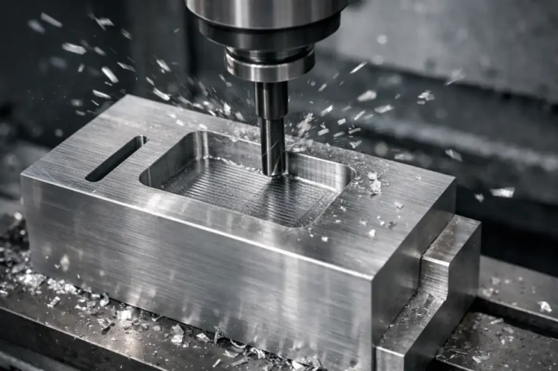
A pocket corner limits both the cutter diameter and the path it can follow. If the same pocket is deep, a small cutter also needs more reach relative to its diameter. That combination can slow machining and make deflection harder to control, even when the corner looks like a minor detail in CAD.
Distinguish the corner you are controlling
A vertical inside corner, the junction of a floor and wall, and an outside edge are different features. They can require different tools and acceptance rules. Mark which radius affects function and whether the value is an exact nominal, a maximum clearance envelope or another controlled requirement.
If a rectangular mating part enters a pocket, inspect its external corner geometry and insertion path. Extra material relief may be acceptable outside the contact surfaces, but that is a design decision. Do not assume that a visually sharp CAD corner must remain sharp at every depth.
Consider the cutter and the holder
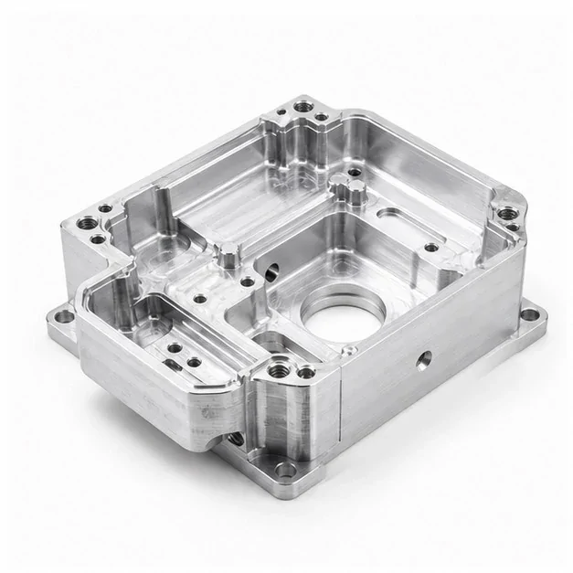
A small inside radius can restrict cutter diameter. When the pocket is also deep, the tool may become long relative to its diameter, increasing sensitivity to deflection and vibration. The holder also needs clearance above and around the feature; a cutter that reaches the floor on its own may still collide when assembled in a holder.
Discuss pocket depth, nearby walls and access direction as one problem. Sandvik's application guidance emphasizes the importance of stable tool assemblies and the effect of overhang. It does not establish a universal minimum corner radius for all HongKe parts. Actual geometry and tooling must be reviewed.
| Parameter | State or show | Review consequence |
|---|---|---|
| Corner requirement | Which corner and the permitted radius envelope | Separates functional limits from incidental CAD detail |
| Pocket depth | Depth from the accessible face | Influences reach and tool overhang |
| Mating geometry | Contact surfaces and insertion path | Determines where a larger radius or relief is acceptable |
| Holder clearance | Nearby walls and approach direction in the model | Checks access beyond the cutting edge |
| Allowed alternatives | Local relief, open access or another route | Requires designer approval before production |
Give the toolpath space to work
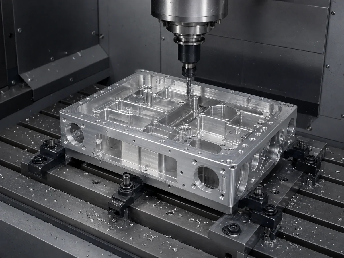
When a cutter is close in size to the corner it must form, engagement can increase as the tool enters the corner. A smaller cutter relative to the permitted corner may allow a more manageable path, but can also require extra passes elsewhere. The practical choice balances stiffness, reach and removal strategy.
Avoid setting one fixed cutter-to-radius ratio without considering the part. Instead, tell the supplier where additional radius or local relief is allowed. For CNC milling, that freedom can be more valuable than specifying an exact tool diameter that unnecessarily constrains process planning.
Compare geometry options
| Review factor | Small internal radius | Larger functional radius |
|---|---|---|
| Tool size | Can limit the cutter diameter | Can permit a larger cutter where function allows |
| Rigidity | A small cutter with long reach is more sensitive to deflection | A larger cutter may improve stiffness; reach still matters |
| Pocket access | Deep pockets may restrict both tool and holder clearance | More corner room can improve the path, but does not remove holder constraints |
| Mating geometry | May be needed to clear a square mating feature | Must preserve insertion clearance, contact and usable pocket area |
A truly sharp internal profile may justify another manufacturing approach. Wire EDM can be relevant to suitable conductive parts and accessible profiles, but it introduces its own geometry and process boundaries. It should be evaluated as a route decision, not offered as an automatic fix for every blind pocket.
Internal Radius Design Flow
- Mating geometry allows a radiusUse the largest internal radius that preserves the required interface.
- Square mating edge needs clearanceAdd a defined relief only at the interference point and dimension it clearly.
- No radius or relief is acceptableReview a different process route with the complete conductive-material and access constraints.
What This Means for Your Part
Provide pocket depth, the mating component and the surfaces that actually contact it. Mark where a larger radius or approved relief is acceptable and where the design must remain unchanged. If the corner carries a stress or sealing requirement, make that constraint explicit before discussing cost reduction.
Ask drawing review to assess cutter reach and holder clearance with the complete model. Include any agreed radius alternatives in your RFQ. The final drawing should state the accepted geometry clearly so that a helpful machining suggestion cannot become an uncontrolled production change.
- Compare every inside corner to the tool diameter that can physically reach it.
- Check pocket depth against the required cutter reach and radius.
- Add a relief only where a mating square edge needs clearance.
References & Further Reading
Source context supports the engineering discussion. Exact product specifications and applicable standards must be confirmed for the part.