Quick Answer
Reduce CNC cost by removing machining and inspection work that does not protect part function. Review setups, tool access, stock selection and tolerance requirements before changing any mating or load-bearing feature.
Key Takeaways
- Combine related features on faces that can be reached in the same setup.
- Use a stock size and material grade that are readily available for the required performance.
- Remove precision, thin sections and deep features that do not serve the assembly.
A small hole on the opposite face can add a complete setup even though it removes little material. A close limit on an unused edge can add measurement work without improving assembly. These costs come from how the drawing defines the job, so review the features, inspection and handling together.
| Design decision | Why it can add cost | What to review |
|---|---|---|
| Tight tolerances everywhere | More process and inspection control may be needed | Identify functional dimensions and relationships |
| Deep narrow pockets | Longer tools and reduced rigidity can affect the route | Improve access where function allows |
| Small internal radii | Smaller cutters may be required | Increase radius or use approved local relief |
| Thin unsupported walls | Deflection and vibration risk can increase | Review wall support, span and clamping |
| Multiple machining orientations | Additional setups and alignment can be required | Combine accessible features where appropriate |
| Cosmetic finish everywhere | Finishing, masking and handling can expand scope | Separate cosmetic and functional zones |
The table identifies questions to review, not automatic redesign rules. Geometry, material condition, quantity, service environment and acceptance requirements determine whether a change is appropriate.
Start With the Features That Cannot Change
Separate functional interfaces, mating surfaces, seals, locating features, alignment relationships and load paths from incidental geometry. A functional surface may need a close limit while an outside clearance face does not. Before discussing a larger radius, thicker local wall or different access direction, identify the assembly feature that the proposal must preserve.
This step prevents a cheap-looking modification from moving cost into assembly. A looser locating bore could reduce machining effort but require selective fitting later. A finish change could simplify manufacture but undermine corrosion protection. Compare alternatives against the same service conditions and acceptance basis.
Reduce Unnecessary Setups
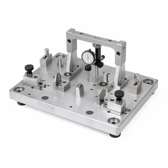
Each machining orientation can introduce workholding preparation, alignment, datum transfer, handling and an inspection decision. Group features that are accessible from the same orientation where function permits. A hole on the opposite face may require a separate setup even when it removes very little material, because the relationship to previously machined features still has to be controlled.
Do not combine operations simply to reduce their count. A critical relationship can require another orientation or a different locating strategy. The useful question is whether the part can be held and referenced in a way that protects the features that matter, while avoiding extra transfers for features that do not.
| Input | What to identify | Why it helps the review |
|---|---|---|
| Functional interfaces | Fits, sealing faces, locating features and load paths | Keeps savings away from features that protect assembly or service |
| Negotiable geometry | Radius, wall, access or feature-location alternatives | Gives the reviewer permission to compare practical routes |
| Acceptance controls | Critical dimensions, finish zones and inspection evidence | Prevents a reduced price from omitting required verification |
| Material and final condition | Grade, condition, treatment and protected areas | Connects stock and finishing scope to the actual function |
| Quantity and repeat demand | Prototype, release quantity and expected repeats | Separates one-time preparation from recurring part cost |
Improve Tool Access and Avoid Long-Reach Cutting
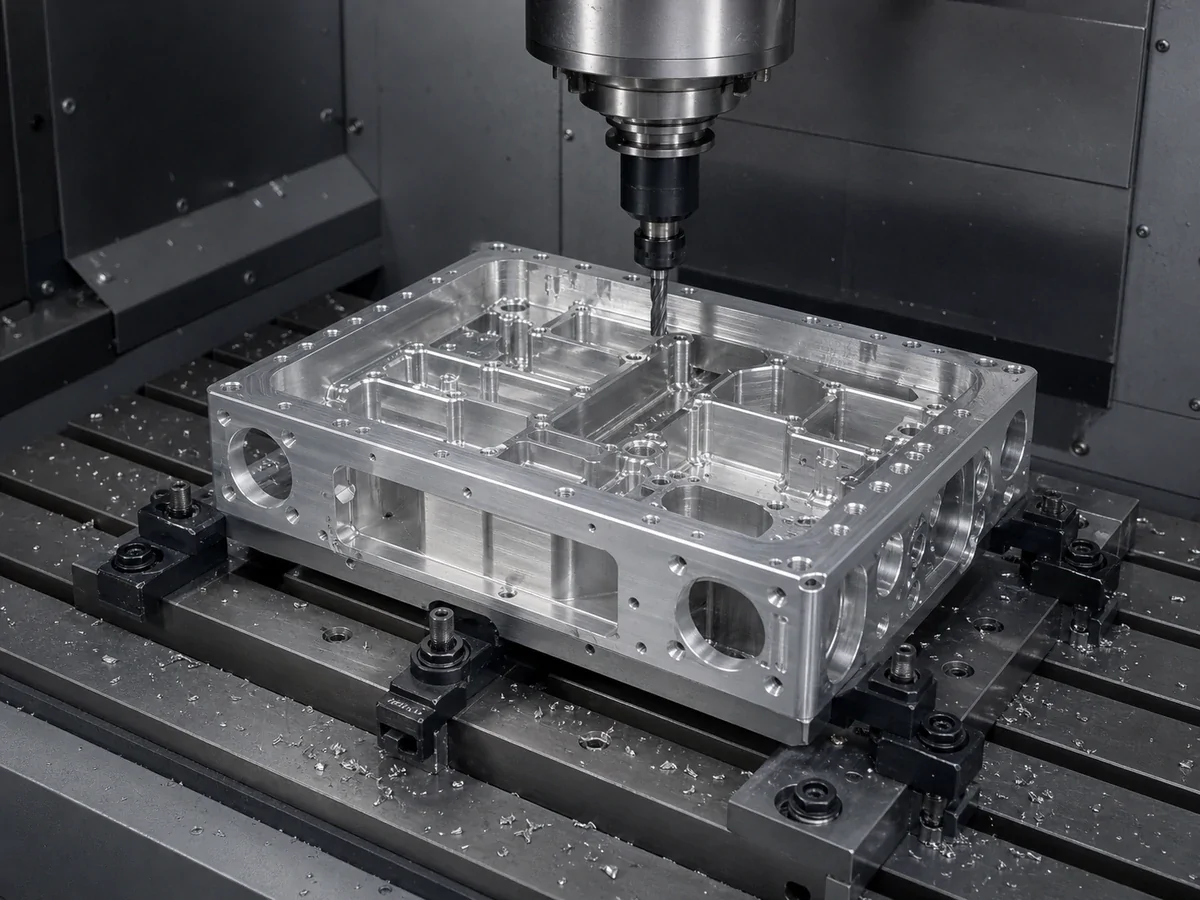
Deep pockets, narrow channels and obstructing walls can force a small cutter to extend farther from its holder. The tool may then deflect or vibrate, requiring lighter cuts and more machining time. For CNC milling, check clearance for the holder as well as the cutting edge.
Ask whether a wall can move, a pocket can open from another direction, or an accessible face can carry the feature instead. These are design choices, so the supplier can identify the manufacturing consequence but the design authority should approve the geometry change.
Use Practical Internal Corner Radii
An internal milled corner normally reflects the radius of the rotating cutter that creates it. A permitted larger radius can allow a larger, more rigid tool; a small radius can require a smaller cutter, extra passes or greater reach. Pocket depth and nearby walls determine whether that difference is meaningful for a particular design.
Review the mating part and its insertion path before allowing a larger corner. When continuous radius is not acceptable, a local relief may be possible outside contact, sealing and load-bearing zones. Internal Corner Radius Design for CNC Machining explains the access questions that should be settled with the complete model.
Keep Thin Walls Only Where They Add Function
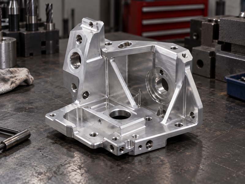
Thin walls can deflect under cutting and clamping forces. A geometry that appears light and efficient in CAD may need careful sequencing, temporary support and extra inspection after release. Consider ribs, shorter unsupported spans or a thicker local section where the assembly envelope allows them.
Do not impose one minimum thickness across every material and shape. Ask the machining reviewer to evaluate unsupported height, adjacent pockets, stock condition and the final tolerance together. If a wall must remain flexible in service, distinguish the free-state requirement from any restrained inspection condition. See Minimum Wall Thickness for CNC Machined Parts for the inputs that change this assessment.
Apply Tight Tolerances Only to Functional Features
A tight tolerance is useful when variation can change fit, sealing, motion, alignment or another functional condition. Applying close limits to every edge may add machining control, measurement effort and process attention while leaving an important relationship unspecified. Define size, position, orientation and form separately where each protects the assembly.
CNC Machining Tolerances: What Can Actually Be Achieved? explains why the same number can be a different manufacturing problem on a short rigid feature and a deep feature behind a thin wall. A clear general tolerance for remaining dimensions helps the quote reflect the real acceptance scope.
Specify the Material the Function Requires
Do not assume that a more expensive, harder or higher-strength material automatically creates a better part. Start from the mechanical requirement, environment, weight, stock availability, machinability and finish. A geometry change may solve a stiffness problem more effectively than a material upgrade; an environment requirement may need a review distinct from strength.
Use the materials overview to frame the required grade, condition and acceptable alternatives. If aluminum selection is open, Aluminum 6061 vs 7075 for CNC Machining identifies the information that should be specified before stock is purchased. Material substitutions remain subject to design approval.
Specify Surface Finish Only Where Needed
Separate functional surfaces, cosmetic faces and areas that need no special treatment beyond normal machining and edge handling. Polishing, blasting, anodizing and plating can add preparation, masking, handling, inspection or scheduling work, depending on the material and the required outcome. A decorative finish on a hidden surface is not automatically a useful requirement.
State which surfaces need texture, appearance or protection, and whether dimensions apply before or after finishing. The CNC Machining Surface Finish Guide helps distinguish a functional texture requirement from a cosmetic appearance request without assigning a universal finish value.
Match Inspection to Critical Characteristics
Inspection effort should follow the consequence of the characteristic. A caliper, micrometer, height gauge or CMM may be considered depending on access, feature geometry, datum simulation, required evidence and measurement uncertainty; no instrument should be assumed from a tolerance alone. State which characteristics need records, whether sampling is required and when the results are needed.
The quality and inspection page describes the available project context. Include the critical feature, accepted condition and evidence requirement in the drawing package so the quotation covers verification as well as machining.
Consider Quantity and Repeat Production
Prototype and repeat production do not have the same cost structure. A one-off part can justify flexible workholding and additional setup attention while the drawing is still changing. A stable repeat release may justify fixture preparation, loading improvements, cycle-time work and a defined inspection plan when those investments protect the expected quantity.
Ask for one-time preparation and recurring part cost to be considered separately. Prototype vs Production CNC Machining explains why a successful early part is not, by itself, a controlled repeat-production route.

What This Means for Your Part
Before changing a design to reduce machining cost, identify which features control fit, which surfaces are cosmetic, which dimensions are inspection-critical, which material properties are actually required, whether quantity justifies dedicated workholding and whether alternative tool access is possible. Mark negotiable features separately from interfaces that cannot change.
For each proposed saving, record what changes, why function is preserved and how acceptance remains demonstrable. If these requirements are clear, a machining supplier can review options without changing the intended function. Send the controlled drawing through manufacturing drawing review and include the approved scope with your quotation request. A lower price is useful only when both parties are pricing the same revision and inspection scope.
- Count the required machining orientations before finalizing the geometry.
- Identify whether a common stock size can meet the finished envelope.
- Flag every feature that needs a long-reach, small-diameter or custom tool.