Quick Answer
Choose a hole and shaft fit from the assembly function: clearance for movement, transition for accurate location, interference for retained torque or load. Then specify the mating dimensions and inspection method together.
Key Takeaways
- Define whether the assembly must slide, locate repeatedly, transmit load or remain permanent.
- Use one fit system consistently across mating drawings and purchased components.
- Account for temperature, coating and assembly force before selecting an interference fit.
- Check both tightest and loosest mating sizes; diameter limits alone do not control alignment.
Two parts can each pass their diameter checks and still fail to assemble as intended. Their allowed sizes may leave too much clearance, create excessive interference or overlook alignment. Review both mating limits together, then check the form, location and finished surface that the joint needs.
Start from the assembly behavior
A clearance relationship leaves space between mating features over the specified size ranges. A transition relationship can produce either clearance or interference within those ranges. An interference relationship intentionally overlaps sizes and requires an appropriate assembly and stress assessment.
Select the limits using the nominal size, materials, temperature, loads, lubrication and mating component requirements. Use the applicable controlled standard or the component manufacturer's specification. A part description alone is not enough to choose a fit class.
| Fit type | Assembly behavior | Design intent | What to verify |
|---|---|---|---|
| Clearance | Space remains between the mating features throughout their size ranges | Allow movement or assembly without pressing | Minimum clearance, maximum play, alignment and finished surfaces |
| Transition | Either slight clearance or interference may occur | Locate the part while controlling the assembly method | Both size extremes, permitted assembly force and removal needs |
| Interference | The permitted sizes overlap and require an appropriate assembly method | Retain the joint for its specified load or torque | Interference range, material stress, engagement, temperature and assembly procedure |
Do the worst-case dimensional check
Compare the smallest hole with the largest shaft to determine the tightest size relationship, then the largest hole with the smallest shaft for the loosest. Keep units and measurement conditions consistent. If the assembly relies on a bearing or purchased insert, start with that supplier's actual mating recommendations.
Remember that size calculations alone do not capture every failure. A bore can be within its diameter limits yet have an unacceptable location, orientation or form. A long engagement can also respond differently from a short pilot. Identify which controls protect the assembly and which are merely convenient drawing defaults.
| Quantity | Calculation | Interpretation |
|---|---|---|
| Minimum size clearance | Smallest permitted hole minus largest permitted shaft | Tightest possible size relationship |
| Maximum size clearance | Largest permitted hole minus smallest permitted shaft | Loosest possible size relationship |
| Always positive clearance | Minimum size clearance is greater than zero | Clearance remains throughout the size ranges |
| Possible clearance or interference | Minimum is negative and maximum is positive | Either assembly relationship can occur |
| Always negative clearance | Maximum size clearance is less than zero | Interference remains throughout the size ranges |
| Zero at a boundary | One extreme equals zero | Boundary contact needs interpretation under the selected fit convention |
Choose the finishing operation after defining the requirement
Do not specify an operation solely because it sounds precise. Reaming does not automatically correct every location problem, and boring does not remove the need for appropriate setup and tool support. Let the supplier propose a route that addresses the complete requirement while preserving any contractually necessary process restrictions.
Account for coatings, temperature and inspection
Define whether size limits apply before or after the final finish. Added or removed material can change the fit, and masking may need to be planned. Different assembly materials can respond differently to temperature, so an ambient shop measurement may not describe the operating relationship by itself.
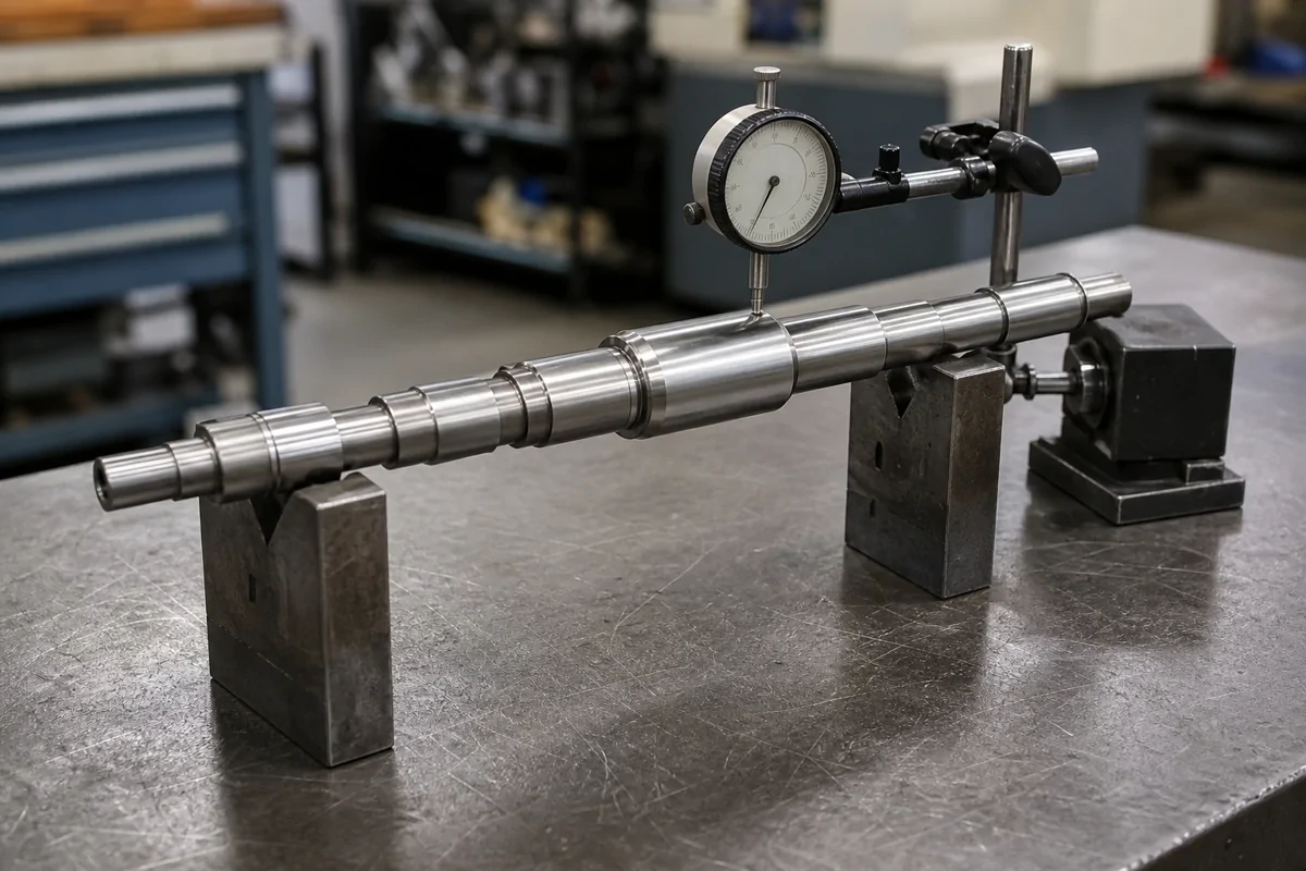
Inspection should match the characteristic. A caliper is not a universal acceptance method for a tightly controlled bore. Discuss accessible contact points, depth, form, sampling and uncertainty with quality planning. If a mating gauge or functional check is required, define its authority alongside dimensional acceptance.
What This Means for Your Part
Provide the mating component or its controlled limits, engagement length, material, finished condition and intended assembly behavior. Identify the datum relationship that places the hole in the part. Reserve close limits for interfaces that need them; extra setup, finishing and measurement can increase cost when a narrow range serves no functional purpose.
Use drawing review to settle ambiguous callouts and precision machining information to frame feasibility. Send the complete relationship through the RFQ page, including any mandatory standard edition or component specification. Numeric fit limits remain an engineering approval item.
- State whether the joint must slide, locate, press together or transmit torque.
- Specify both mating feature limits instead of only one side of the fit.
- Consider coating thickness, temperature range and assembly method before release.