
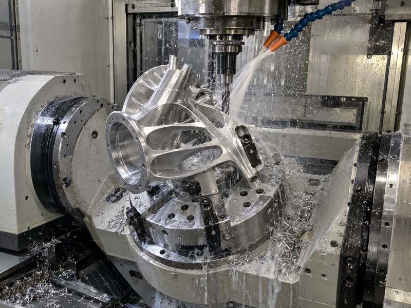
Why Thin-Wall Machining Is a Common Problem
Thin-wall parts are among the most difficult geometries to machine consistently. When the wall thickness drops below a certain range—typically under 1.5 mm depending on material and part size—the part becomes less rigid. During cutting, the cutting force pushes against the wall, and the wall deflects instead of staying in position. This deflection causes several problems: the machined surface may be out of tolerance, tool marks appear, tool wear increases, and in severe cases, the part can be scrapped entirely.
This is not a machine accuracy problem. A 5-axis CNC machine with micron-level positioning can still produce a defective thin-wall part if the cutting forces, material behavior, and fixturing are not considered together. Understanding why thin walls deform, and what can be done about it, is essential for both design engineers and procurement professionals.
Why Thin Walls Deform During CNC Machining
Deformation in thin-wall machining is caused by the interaction between cutting force, material rigidity, and the workholding method.
Cutting Force and Material Rigidity
When a cutting tool engages the material, it exerts a force on the wall. If the wall is thick and rigid, this force is absorbed without noticeable movement. But when the wall is thin, the same force causes elastic deflection. The wall bends away from the tool. After the tool passes, the wall springs back. This springback leaves material on the surface, resulting in a non-flat or oversized wall.
Heat Generation
Thin walls have less mass to absorb the heat generated during machining. As the temperature rises, the material expands locally. This thermal expansion changes the effective wall thickness during cutting. When the part cools, the machined surface becomes undersized or uneven. In materials like aluminum, which have high thermal conductivity, the effect is less severe. In stainless steel or titanium, heat buildup can cause significant dimensional variation.
Workholding Limitations
Thin walls are difficult to clamp firmly without causing distortion before cutting even begins. A standard vise or clamp can squeeze the part out of shape. Once machined and released, the part springs back to its original shape, and the machined surfaces are no longer flat or parallel. This pre-load distortion is one of the most common causes of thin-wall part rejection.
Tool Deflection
When machining deep thin walls, the tool itself may be long and slender. A long end mill deflects under cutting load. The deflection changes the actual depth of cut along the wall height. This results in a tapered surface rather than a straight wall.
Design Considerations for Thin-Wall Parts
Before the first chip is cut, the part design has already influenced how difficult the machining will be. A few design decisions can significantly improve machinability.
Minimum Wall Thickness Guidelines
As a general engineering reference, for aluminum parts, a wall thickness below 0.8 mm becomes very difficult to machine without deformation. For stainless steel, the practical minimum is typically around 1.0 mm. For titanium, 1.2 mm or more is often required. These values depend on wall height, part geometry, and the machining strategy used. Taller walls need greater thickness to maintain rigidity. When the part design requires very thin walls, discuss the geometry with your CNC machining supplier early in the design phase.
Avoid Unnecessarily Tall Thin Walls
The ratio of wall height to wall thickness is a critical factor. A 10 mm tall wall that is 1 mm thick has a height-to-thickness ratio of 10:1. This is already challenging. Above 15:1, even with careful strategy, deformation risk increases sharply. Where possible, design walls with lower height or add stiffening ribs. Ribs add material only where needed and can be machined away later if the design requires an open area.
Add Machining Allowances
If the final wall thickness must be very thin, consider adding a temporary machining allowance. The part can be machined with thicker walls first, then the excess material is removed in a final finishing pass. This two-stage approach reduces the time the wall spends in a weak condition during roughing.
Internal Corner Radii
Sharp internal corners concentrate stress and also force the use of a small-diameter tool. A small tool deflects more easily. Specifying a generous internal radius—where functional—allows a larger, more rigid tool to be used. This reduces tool deflection and improves surface finish on the thin wall.
Machining Strategies to Reduce Thin-Wall Deformation
Once the part design is finalized, the machining process itself offers several ways to control deformation.
Use Multiple Roughing and Finishing Passes
Removing all the material in one pass generates high cutting force. Instead, use multiple roughing passes that remove material gradually. Leave a finishing allowance of 0.2 mm to 0.5 mm (depending on material and wall height). Then take a light finishing pass. A light finishing pass produces less cutting force, reduces deflection, and improves surface quality.
Climb Milling vs. Conventional Milling
Climb milling generally produces lower cutting forces and better surface finish on thin walls. In climb milling, the chip thickness decreases at the end of the cut, reducing the force that pushes the wall away. Conventional milling can cause the tool to push the wall more aggressively, increasing deflection.
Tool Selection and Toolpath Strategy
Use the largest diameter tool that can access the feature. A larger tool is more rigid and deflects less. When machining deep thin walls, consider using a tool with a variable helix or a roughing end mill to reduce cutting forces. For finishing, a ball end mill or a wiper insert can produce a better surface finish with lower force.
Toolpath strategy also matters. Trochoidal milling or peel milling toolpaths distribute cutting forces more evenly. These toolpaths keep the tool engagement angle low, reducing the instantaneous load on the thin wall. They are particularly useful when machining thin walls in materials like stainless steel or titanium.
Controlling Heat Generation
Use coolant effectively to remove heat from the cutting zone. In thin-wall machining, heat buildup is a major cause of dimensional variation. Through-spindle coolant or high-pressure coolant can help. In some cases, using a minimal quantity lubrication (MQL) approach reduces thermal shock but requires careful process control. For aluminum, a steady coolant flow is usually sufficient. For stainless steel and titanium, consider using a coolant with higher lubricity to reduce friction and heat.
Workholding Strategies for Thin-Wall Parts
Workholding is often the most critical factor in thin-wall machining success. The goal is to restrain the part without causing pre-load distortion.
Soft Jaws and Custom Fixtures
Soft jaws can be machined to match the part contour. When the jaws contact a larger surface area, the clamping pressure is distributed, reducing localized deformation. For thin-wall parts, it is common to machine soft jaws to exactly fit the part shape. This method works well for rectangular or prismatic parts.
For more complex geometries, custom fixtures and jigs may be required. Vacuum fixturing is a popular choice for thin flat parts. The vacuum holds the part evenly across its surface, eliminating the need for mechanical clamps. However, vacuum fixturing requires a sealed surface and is less effective for parts with holes or deep pockets.
Adhesive or Double-Sided Tape
For very thin parts, adhesive methods can be used. The part is bonded to a carrier plate with cyanoacrylate adhesive or double-sided tape. After machining, the part is released with heat or solvent. This method completely avoids clamping distortion but requires careful handling and clean surfaces.
Use a Minimal Clamping Force
When mechanical clamps are unavoidable, use the minimum force required to hold the part. A torque wrench on the vise or clamp can help standardize the clamping force. Over-clamping is a common mistake that causes the part to distort immediately.
Machine in a Stress-Free State
If possible, machine the thin wall in a stress-relieved condition. Some materials, especially aluminum and steel, have internal residual stresses from prior processing. If these stresses are not relieved, they can cause the part to warp after material removal. A stress-relieving heat treatment before machining can reduce this risk.
Inspection Challenges for Thin-Wall Parts
Thin-wall parts present unique inspection challenges. The same forces that cause deformation during machining can cause errors during measurement.
Measurement Without Contact
Contact measurement methods—such as a CMM touch probe or a micrometer—can deform the thin wall during measurement, leading to incorrect readings. Where possible, use non-contact measurement methods like laser scanning, vision systems, or air gauging. If contact measurement is unavoidable, use a very low probing force and measure at multiple points to detect deformation.
Check at Temperature
Because thin walls respond quickly to temperature changes, allow the part to reach thermal equilibrium before measurement. A part that is still warm from machining will measure differently than a part at room temperature. Standard practice is to let the part sit in the inspection area for at least 30 minutes before measuring critical dimensions.
Inspect After Unclamping
The part shape may change after it is released from the fixture. Always perform final inspection on the part in a free state, not while it is still clamped. This is the only way to confirm that the machined dimensions are correct for the final application.
How Procurement and Engineering Should Evaluate Thin-Wall Parts
When you are sourcing custom machined parts with thin-wall features, there are several things to discuss with your precision CNC machining supplier.
Provide Complete Drawing and GD&T
A full 2D drawing with clear GD&T is essential for thin-wall parts. Indicate which surfaces are critical and the allowable tolerance. If the wall is structural, the drawing should reflect the functional requirement rather than a default tight tolerance. Over-tolerancing a thin wall can lead to unnecessary cost and scrap.
Discuss Material and Machining Strategy
Different materials behave differently in thin-wall machining. A supplier experienced in aluminum CNC machining may give different advice than one who primarily machines steel. Ask your supplier how they plan to fixture the part, how many setups are needed, and what tooling they intend to use. A clear process plan is a sign of an experienced machining partner.
Understand the Risk of Scrap
Thin-wall parts have a higher scrap rate than standard parts. This risk can affect both cost and lead time. A responsible supplier will quote based on realistic yield expectations, not ideal conditions. Expect a slightly higher price and longer lead time for thin-wall parts, especially in difficult materials.
Confirm Inspection Capability
Not all inspection methods are suitable for thin walls. Confirm that your supplier has non-contact measurement capability if your tolerances are tight. Discuss the inspection plan before production begins so there are no surprises at the final quality gate.
Final Thoughts on Thin-Wall Machining
Thin-wall machining is a balancing act between part design, material selection, cutting strategy, and workholding. There is no single solution that works for every part. The key is to understand how each factor contributes to deformation and to make intentional choices that reduce risk.
For design engineers, the most effective step is to avoid unnecessarily thin walls and include features like stiffening ribs or generous corner radii. For procurement professionals, the most important step is to choose a machining partner who understands thin-wall challenges and can discuss fixturing, toolpath, and inspection in detail.
When the design is practical and the machining approach is well-planned, thin-wall parts can be produced consistently within tolerance. The difference between a successful thin-wall part and a scrapped one is often not the machine—it is the understanding of how the wall behaves during cutting.