
Choosing between 3D printing and CNC machining is rarely about which process is more advanced. It is about which one fits your geometry, tolerance requirements, material, and order quantity. The two routes fail in different ways, and their cost curves cross at a point you can estimate before you commit to a quoting cycle.
This comparison stays on the engineering and purchasing side: what each process delivers, where it breaks down, and how to decide when both could produce a working part.
Where the Two Routes Actually Diverge
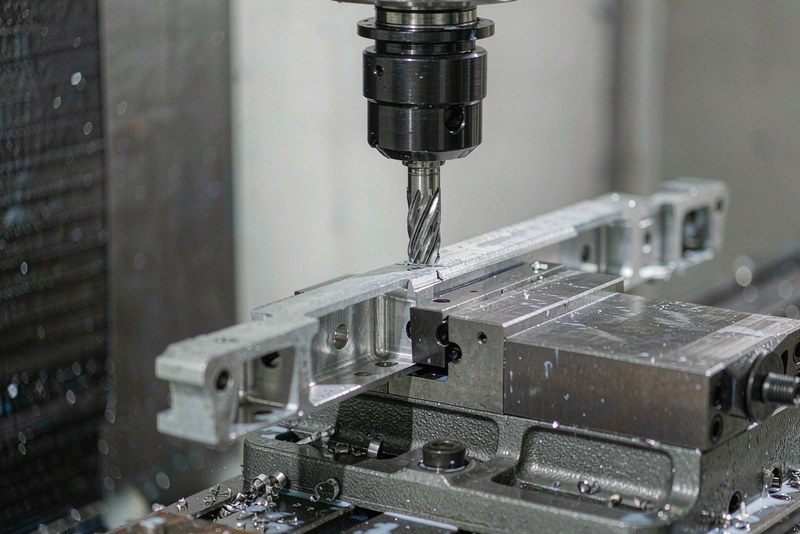
Additive processes build a part layer by layer, from polymer filament, photopolymer resin, or a metal powder bed. CNC machining starts from solid stock and removes material with cutting tools.
That one difference drives most of the trade-offs. With no cutter pushing through the workpiece, there is no cutting force to deflect a thin wall or a slender rib, so geometry that would chatter on a machine can be built directly. With no melt-and-solidify step, the material that leaves a machining center is the material that entered it, with the wrought properties of the stock form intact. The same logic governs any multi-process decision, including choosing between cold heading, stamping, and CNC machining: the route is set by whichever constraint dominates the part.
Tolerances and Surface Finish: What Each Route Can Hold
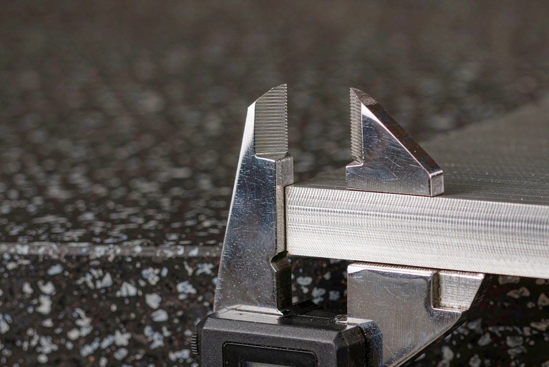
A printed feature and a machined feature do not sit in the same band. Printer accuracy depends on layer thickness, beam or nozzle path, shrink compensation, and build orientation, so the same nominal feature can measure differently depending on the direction it faced. Machined features are cut against a fixture with the tool following a controlled path, so variation is usually smaller and easier to predict.
That does not make additive inaccurate, only less predictable: a printed tolerance has to be confirmed on a first article rather than read off a datasheet.
Surface texture follows the same pattern. Curved and angled printed faces carry layer stair-stepping, which can hold residue or read as a witness mark on a sealing face. Machined faces carry a directional lay from the cutter path; a controlled texture can be produced on selected critical features, though the achievable value depends on material, geometry, workholding, process route and inspection requirements.
Material Behavior: Anisotropy, Porosity, and Heat Treatment
Printed parts often behave differently depending on load direction. Extruded and powder-bed processes build material in planes, and the bonds between those planes are usually the weak link, so a part can pass a pull test in one orientation and delaminate in another. Ignore that and you end up with a component that looks correct on a drawing and fails in service.
Machined parts cut from wrought stock have no interlayer bonds to pull open. Cast and forged forms bring their own grain flow, but that is a known variable a machinist works around rather than a build parameter.
Porosity is the other frequent surprise: printed metal can retain internal voids that matter for pressure-tightness and fatigue life, a variable that cutting from solid stock removes.
Geometry: Where Additive Holds the Advantage
Some shapes have no practical machining answer. Internal conformal cooling channels that follow a curved surface, lattice structures, and merged organic ribbing can be printed in a single build and cannot be reached by a tool. If a part depends on those features for its function, additive is the starting point and machining becomes the finishing step.
The reverse is just as common. A deep straight-walled pocket with a small corner radius is straightforward to mill and awkward to print, because the printer has to resolve the corner layer by layer while the cutter simply follows a path. Mostly prismatic parts, or parts needing a flat datum face and a bolt circle, usually land on the machined side. Thin walls are the grey area: printing avoids cutter deflection, while machining can still work with the right sequence and support.
3D Printing vs CNC Machining: Where the Cost Crossover Sits
Additive has a low entry cost and a comparatively flat unit cost. There is no workholding to design, and one more printed part usually costs about as much as the last one. Machining carries a higher entry cost — programming, fixturing, and a first-article check — but the unit cost falls as that setup is amortized, which is largely what the price breaks in a machining quote are paying for.
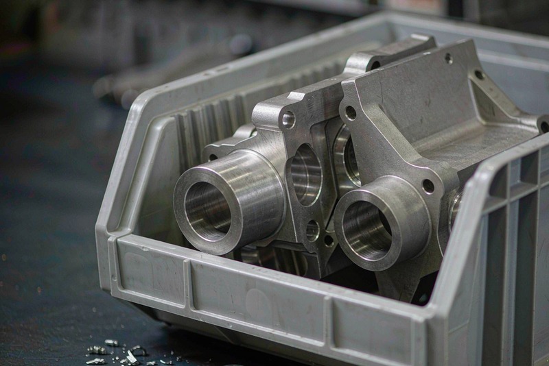
The crossover is therefore not a fixed quantity. It moves with part size, material cost, the number of features requiring inspection, and how much of the part can be cut in one setup. A small bracket with simple features can cross into machining territory at low volumes; a palm-sized part with an internal channel may not cross at all. Ask both routes for cost at three quantities rather than one, and the curves become visible.
Lead Time and the Cost of Late Design Changes
The first article is where the two routes separate most clearly. A printed part can be re-run after a design change with no tooling to touch, so iteration cost stays close to the cost of material. A machined part usually means revisiting the program and the workholding, which is why lead time in CNC machining depends on when the drawing stops changing, not only on the machine schedule.
On a project still in flux, a common split is to print the form-and-fit units and machine the parts that carry critical interfaces. That keeps iteration cheap where the design is moving and puts the tolerance where the function needs it.
A Decision Checklist Before You Commit
Answer these in order before you send a part out. The first question that produces a firm constraint usually settles the route.
- Does any feature need an internal channel or lattice that a cutter cannot reach from any setup?
- Does the part have to hold a pressure boundary?
- Is a tight tolerance required on selected critical features, and does it land on a mating surface?
- Does the load path run through interlayer bonds or through wrought material?
- Is the quantity likely to grow once the design is frozen?
- Can the interface features be machined while the rest stays printed?
When the answers point in two directions, quoting both routes costs less than guessing wrong.