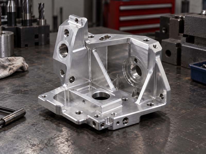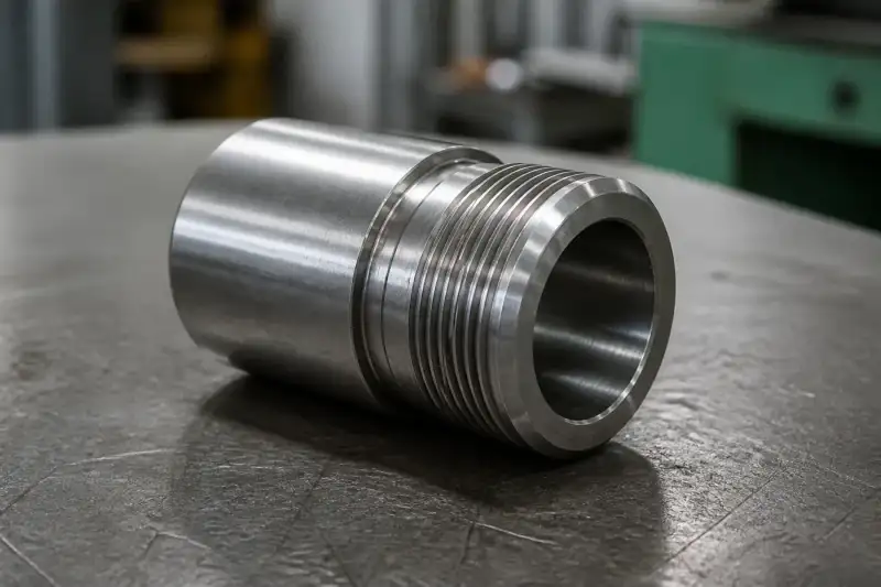
Quick Answer
Choose thread size, engagement and access from the load path and assembly method. Use standard threads where possible, provide realistic tool runout and avoid placing critical threads where finishing or inspection cannot reach them.
Key Takeaways
- Specify the thread standard, size, class and depth in the drawing callout.
- Leave enough clearance for taps, thread mills, runout and gaging.
- Review whether an insert is needed for repeated assembly in the selected material.
- Distinguish usable full-thread depth from the overall depth of a blind hole.
- Confirm whether thread acceptance applies before or after the final surface treatment.
The bottom of a drilled hole is not the end of its usable thread. Tools need entry, runout and clearance, and the mating fastener must engage without bottoming out. Show the required engagement and surrounding geometry so the supplier can plan the thread without weakening a nearby wall or shoulder.
Thread Specification Checklist
- Thread system: identify the governing standard and designation.
- Size: state the nominal size from the selected thread system.
- Pitch: specify pitch or threads per inch as required by that system.
- Internal or external: identify the threaded feature and handedness where needed.
- Blind or through: show the hole end and any nearby passage or bottom wall.
- Usable depth: separate full-thread engagement from total drilled depth.
- Relief: dimension approved runout or shoulder clearance where needed.
- Insert: specify the exact insert and installation requirements if included.
- Class: state the required class and standard edition where applicable.
- Inspection: define the gauge or method and the final treatment stage.
Define the thread rather than a modeled helix
Specify whether the feature is internal or external, its designation and pitch, any applicable class, handedness where needed and required length or depth. Metric, UNC and UNF are different thread systems; do not combine elements from different conventions. Use the applicable controlled standard or mating component specification for numeric limits.
A CAD thread may show only its location and appearance. Put the class, usable depth and inspection requirement on the drawing, including the standard edition if the purchase contract requires one.
| Parameter | Specify | Keep distinct from |
|---|---|---|
| Thread system | Governing designation and standard | A visual CAD helix |
| Size and pitch | Nominal size and pitch or threads per inch as applicable | Values borrowed from a different thread system |
| Class and handedness | Required class and handedness where needed | An unstated supplier assumption |
| Usable full thread | Required engagement length or full-thread depth | Total drilled-hole depth |
| Blind-hole envelope | Overall depth and surrounding bottom/wall geometry | An assumed fixed allowance below the thread |
| Runout or relief | Approved transition at the end or shoulder | An uncontrolled geometry change |
| Finished acceptance | Treatment stage, gauge/method and evidence scope | Inspection of the unfinished thread only |
Leave space beyond usable engagement
A blind hole needs room for the chosen process to produce the specified full thread. Tool geometry, chip space and drill-point geometry can make total hole depth different from usable threaded depth. If the bottom wall is thin or another passage is close, show that relationship clearly.
Do not extend engagement simply because the available solid model permits a longer hole. Extra depth can add tool reach, chip-control and inspection difficulty without providing proportional assembly benefit. The designer should establish the necessary engagement from the joint, material and fastener requirements.
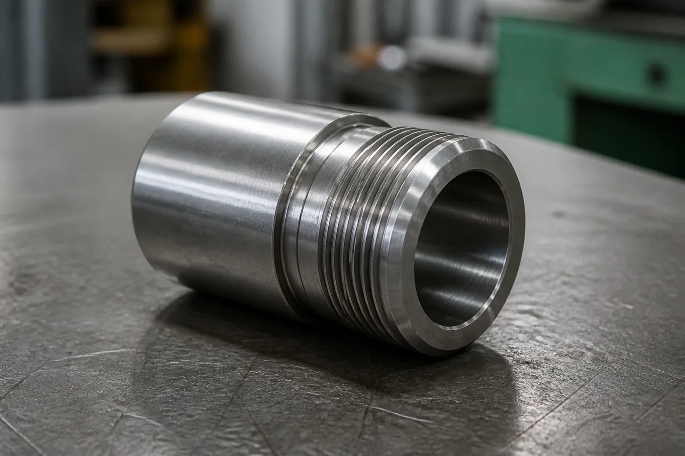
Review external runout and shoulder clearance
An external thread that approaches a shoulder needs a defined transition. The mating component may require room to seat fully, while the machining tool needs a practical way to finish or exit. A relief can help in some designs, but its effect on strength, sealing and assembly must be approved.
For CNC turning, also consider workholding and the relationship between the threaded feature and nearby diameters. Specify the datum or axis relationship when it matters to function. An accurate thread size is not a substitute for the necessary alignment control.
Decide whether an insert is part of the design
| Requirement | Information needed |
|---|---|
| Direct tapped hole | Material, designation, usable depth and mating fastener |
| Threaded insert | Exact insert system, installation requirement and acceptance |
| Thread after finishing | Final condition, coating allowance or masking requirement |
| Verification | Gauge or method required, evidence scope and accessibility |
An insert adds preparation, installation and inspection work. Name the actual product, include its installation requirements and confirm availability before releasing the machining package.
Include final finish and inspection
A coating or other treatment can alter the thread's mating behavior. State whether inspection occurs before or after finishing and whether any areas require protection. Ask the supplier to confirm the final route; do not assume that a nominal allowance can be applied to every treatment.
If a functional gauge is required, define the governing requirement and whether recorded evidence is needed. Some internal features are difficult to inspect at full depth. Address these questions through quality planning rather than leaving them until a completed batch is ready to ship.
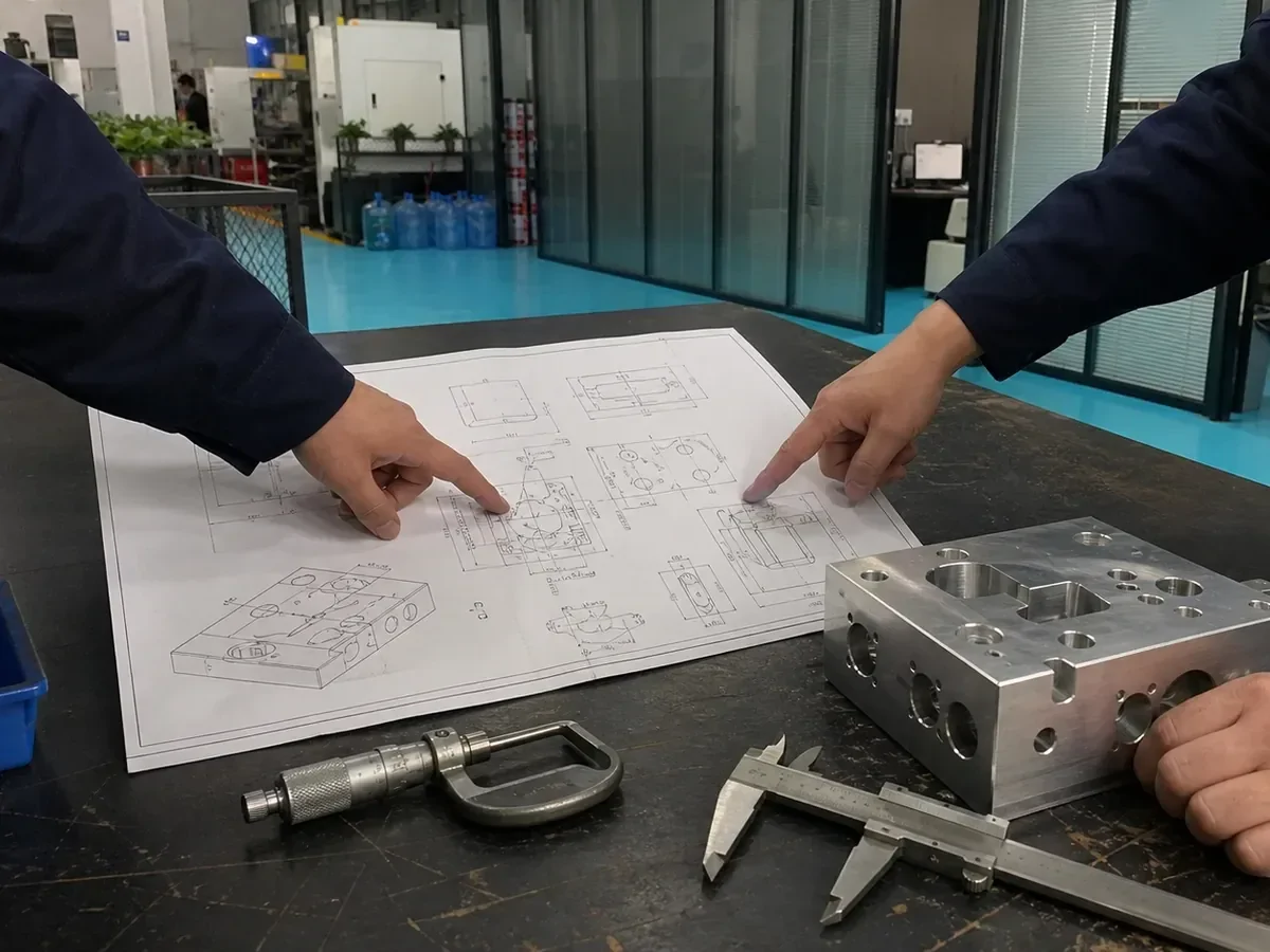
What This Means for Your Part
Send the controlled callout, mating component, usable engagement, surrounding wall geometry and final finish. Mark any relief or depth that may be proposed for approval. Use drawing review to separate the designer's functional requirement from process details the supplier should recommend. Your RFQ should include inserts and inspection as explicit scope items, not assumptions hidden behind a thread symbol.
- State thread standard, nominal size, pitch, class and required engagement depth.
- Check tool entry, thread runout and gage access at every threaded location.
- Identify joints that need inserts because of repeated service or lower-strength material.
References & Further Reading
Source context supports the engineering discussion. Exact product specifications and applicable standards must be confirmed for the part.